Section 6 Correction Software
6-34
(7) To measure the correction values of the DUT, set the command button of section
[14] at “Calibration.” On the other hand, to measure the frequency response, set
the command button at “Freq. –– Resp.”
(8) Check all the setup items and click the “Measure” button of section [15]. This
causes the measurement to start after confirmation of the contents set prior to
measurement start. See 6.7.4 “Items Confirmed Before Start of Measurement”
for more information on the items that must be confirmed prior to measurement
start.
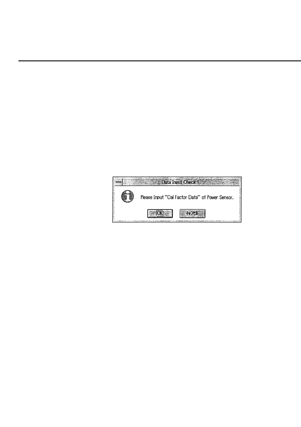
(9) When the measurement starts, a message requesting confirmation of the power
sensor Cal factor input, as shown in Fig. 6-28, is displayed. Select a power sensor
and input a Cal factor in the manner described in 6.6.10 “Inputting Power Sensor
Cal Factor.”
Fig. 6-28 Cal Factor Input Confirmation Message
(10) Following completion of initial setting of the DUT, a message requesting confir-
mation of the connection of the measurement system is displayed. Perform rel-
evant operations in the manner described in 6.6.9 “Connection Confirmation
Message Display.” This causes the measurement to start. When the measurement
of both output terminals is selected on the “Initial Menu Screen” shown in Fig. 6-
4 at the same time, a message requesting confirmation of the connection will be
displayed following the completion of the measurement of the Main terminal.
Switch the connection and restart the measurement accordingly. When the mea-
surement is completed, the screen returns to the “Initial Menu Screen” shown in
Fig. 6-4.