Section 6 Correction Software
6-36
(10) When the measurement starts, an output calibration selection screen for the signal
generator is displayed. This enables selection of calibration of the data file to be
used for measurement. See 6.7.3 “Procedures for Signal Generator Calibration”
for more information on the calibration of the signal generator.
(11) When the number of DUTs selected to be measured is set at one unit on the
“Initial Menu Screen,” shown in Fig. 6-4, a connection diagram is displayed in
the manner described in 6.6.9 “Connection Confirmation Message Display”.
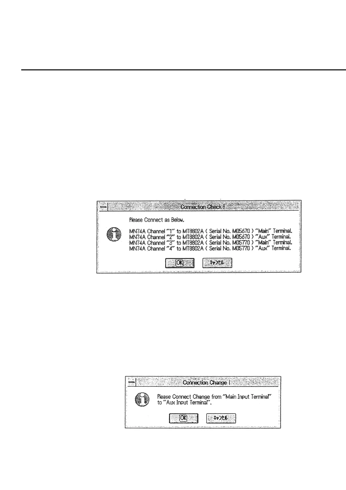
However, when continuous measurement of multiple DUTs is selected, a mes-
sage as shown in Fig. 6-29 “Message Requesting Confirmation of Connection of
Reception System” will be displayed. Connect the input terminal displayed in
each channel of the channel selector with a cable (with a 3 dB attenuator) and
click the “OK” button. When the “Cancel” button is selected, the screen returns
to the “Initial Menu Screen” shown in Fig. 6-4 without performing measurement.
Fig. 6-29 Message Requesting Confirmation of Connection of Recep-
tion System
(12) If the measurement was started without using the channel selector from the “Ini-
tial Menu Screen,” shown in Fig. 6-4, the “Message Requesting Confirmation of
Switching in Connection,” shown in Fig. 6-30, appears when the measurement of
all the items of the Main input terminal is completed. Switch the connection of
the measurement system and click the “OK” button. This causes the measure-
ment of the Aux input terminal to start. When the “Cancel” button is selected, the
measurement is suspended and the screen returns to the “Initial Menu Screen”
shown in Fig. 6-4.
Fig. 6-30 Message Requesting Confirmation of Switching in Connection