Assembly Removal and Replacement, MS202xC 6-25 Installing Main PCB and Reassembling Instrument
MS20xxC MM PN: 10580-00307 Rev. D 6-53
4. Fasten the Main PCB into place with seven (7) hex standoffs and two (2) pan head screws. Torque these
standoffs and screws to 7.5 lbf·in (0.85 N·m).
5. Connect the Battery Power cable to J1003 and the Fan cable to J1002 on the Main PCB (both cables are
visible in Figure 6-20, and the connectors are shown as item_12 and item_13 in Figure 6-16
on page 6-34).
Installing GPS Receiver Module:
6. If the GPS Receiver Module (Option 31) is not installed, then skip ahead to Step 7. If it is installed, then
perform the following sub steps:
a. Carefully position the replacement GPS Receiver Module so that it is lined up with its mounting
standoff holes and 14-pin header connector on the Main PCB.
b. Use extreme care so as to not bend any of the header pins.
c. Be careful to not offset the header pins by one row.
d. Make sure that the header pins are loosely but correctly positioned before proceeding.
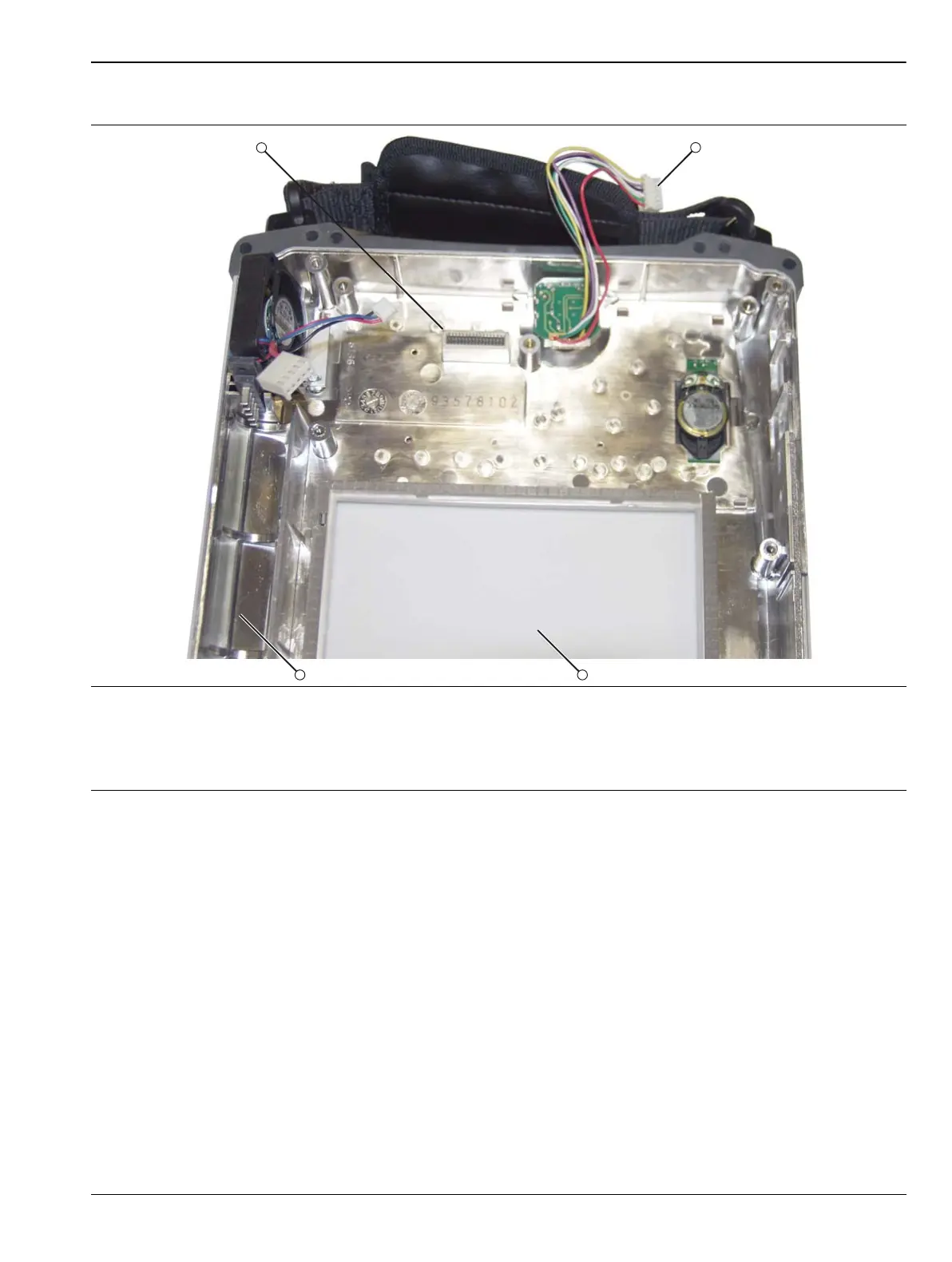
1. Connector J1 of Main Keypad Assembly (mates with J5006 on Mother Board)
2. Rotary Knob Connector (mates with J5010 on Mother Board)
3. Clear Plastic LCD Protector
4. Battery Compartment Section of Case Front
Figure 6-20. Front Case without Mother Board

 Loading...


