7-13 Replacing Main Menu Keypad Components Assembly Removal and Replacement, MS203xC
7-20 PN: 10580-00307 Rev. D MS20xxC MM
Removing Main Keypad Bezel:
5. The Main Keypad Bezel and Membrane must be removed to access the connector on the Main Keypad
PCB.
The Main Keypad PCB does not need to be removed in order to service the Main Menu Keypad assembly.
6. Eight (8) locking tabs hold the Main Keypad Bezel to the case as shown in Figure 7-11
7. Using a small flat blade screwdriver and a small piece of rubber or similar material, carefully pry the
eight (8) Main Keypad Bezel locking tabs free of the main body of the case. The following tips help with
the removal process:
• The flat blade screwdriver width must be less than 3.5 mm (0.13 inch) wide and as thin as
possible. If available, recommended is a screwdriver made of fiberglass or other material that will
not scratch the bezel.
• As each locking tab releases, the bezel comes up a bit.
• The basic technique is to move the protective piece of rubber (or similar material) next to the slot,
press the screwdriver straight in between the case and the bezel, and then gently lever the
screwdriver AWAY from the bezel using the rubber as protection for the case finish.
Protecting Speaker Removing Bezel:
8. When the eight locking tabs are released, lift the bezel carefully up, disengage the speaker from its
mounting pins (it stays attached to the underlying Main Keypad PCB, and set the bezel aside.
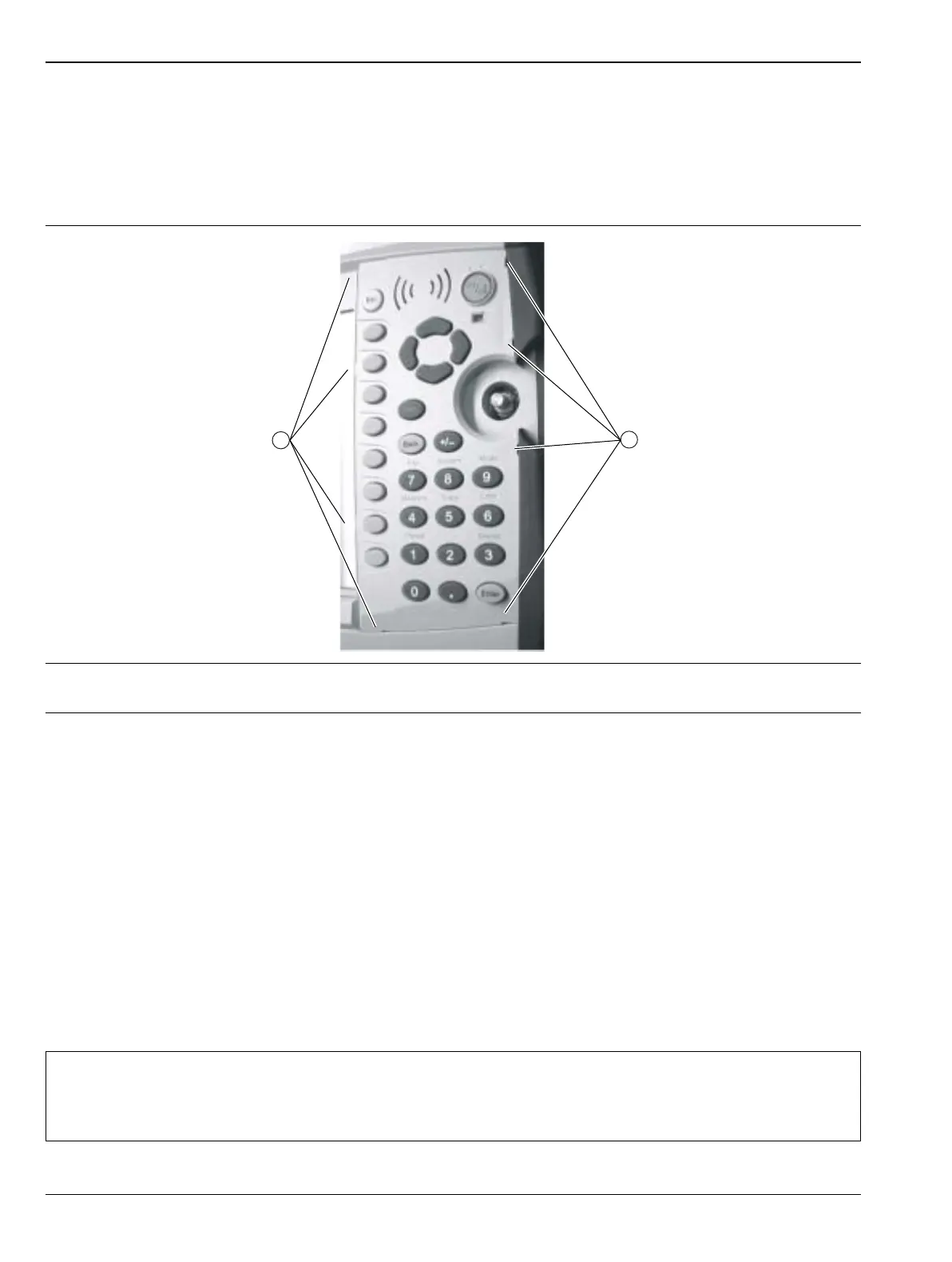
1. Location of four (4) left side locking tabs on the Main Keypad Switch Bezel.
2. Location of four (4) right side locking tabs.
Figure 7-11. Locking Tab Locations for Main Keypad Bezel
Caution
The Speaker sits on top of the Main Keypad PCB and is held in place by four locating pins on the
inside of the keypad bezel around the speaker opening. When the keypad bezel is removed, the
speaker is held only by the fragile connecting wires. Use care not to damage the speaker wires when
removing or replacing the keypad rubber Membrane or PCB.

 Loading...


