Assembly Removal and Replacement, MS203xC 7-20 Replacing Rotary Encoder – 3-410-101
MS20xxC MM PN: 10580-00307 Rev. D 7-51
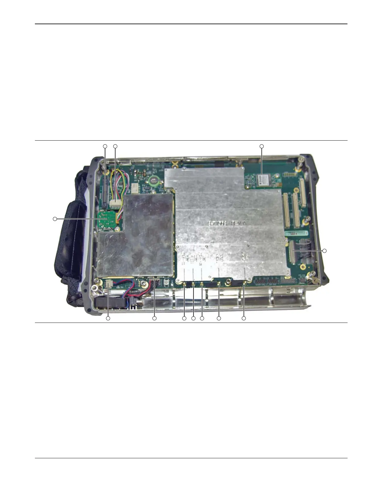
Removing Coaxial Cables:
11. Using needle-nose pliers, remove the 2 attached coaxial cables from the Main PCB Assembly at the
following locations. Leave the cables attached to the VNA PCB Assembly.
• J2201 26 MHz Out – Cable connected to the top RF shield on the VNA Module.
(MCX connectors)
• J3202 Trig In – Cable connected to the Ext Trig In BNC connector on the top connector panel of
the VNA PCB Assembly and an MMCX connector on the Mother Board. Refer to Figure 7-19 on
page 7-39 for coaxial cable connections between the VNA PCB Assembly and the Main PCB
Assembly.
12. Carefully lift the VNA PCB Assembly and fold it over on top of the SPA PCB in the Case Bottom
Assembly. Arrange the VNA PCB Assembly so that the remaining cables are not stressed.
Removing the Rotary Encoder:
Figure 7-24. Mother Board (Main PCB) Connections

 Loading...


