Assembly Removal and Replacement, MS203xC 7-25 Installing Main PCB and Reassembling Instrument
MS20xxC MM PN: 10580-00307 Rev. D 7-75
18. The two halves of the instrument can now be safely joined. The Case Back Assembly contains the
Spectrum Analyzer (SPA) board. The Case Front Assembly contains all of the other serviceable parts.
19. Ensure that the 4 RF cables (connecting case front and case back) are safely tucked in along the bottom of
the Mother Board.
Closing the Case Assembly:
20. Replace the Case Back Assembly on top of the Case Front Assembly, making sure that the top connector
panel is correctly centered in its mounting groove and that all cables are clear.
21. Ensure that the SPA RF In connector mounting plate is properly engaged within the top connector panel.
Ensure that the top connector panel is correctly centered in its mounting groove and that all cables are
clear.
a. Insert and tighten the four SPA connector plate mounting screws (refer to item 6 in Figure 7-40).
Torque these screws to 4.0 lbf·in (0.45 N·m).
b. Insert and tighten the four case mounting screws (refer to Figure 7-40). Torque the screws to
7.5 lbf·in (0.85 N·m).
Caution
All cables along the lower edge of the Mother Board and VNA PCB Assembly must be routed in such
a manner that they will not be pinched between, or protrude between, the case halves of the upper
battery compartment. If any cable protrudes into the battery compartment when the case is closed,
then the cable may be damaged by pinching, or by the battery when it is inserted, or it may prevent
battery insertion.
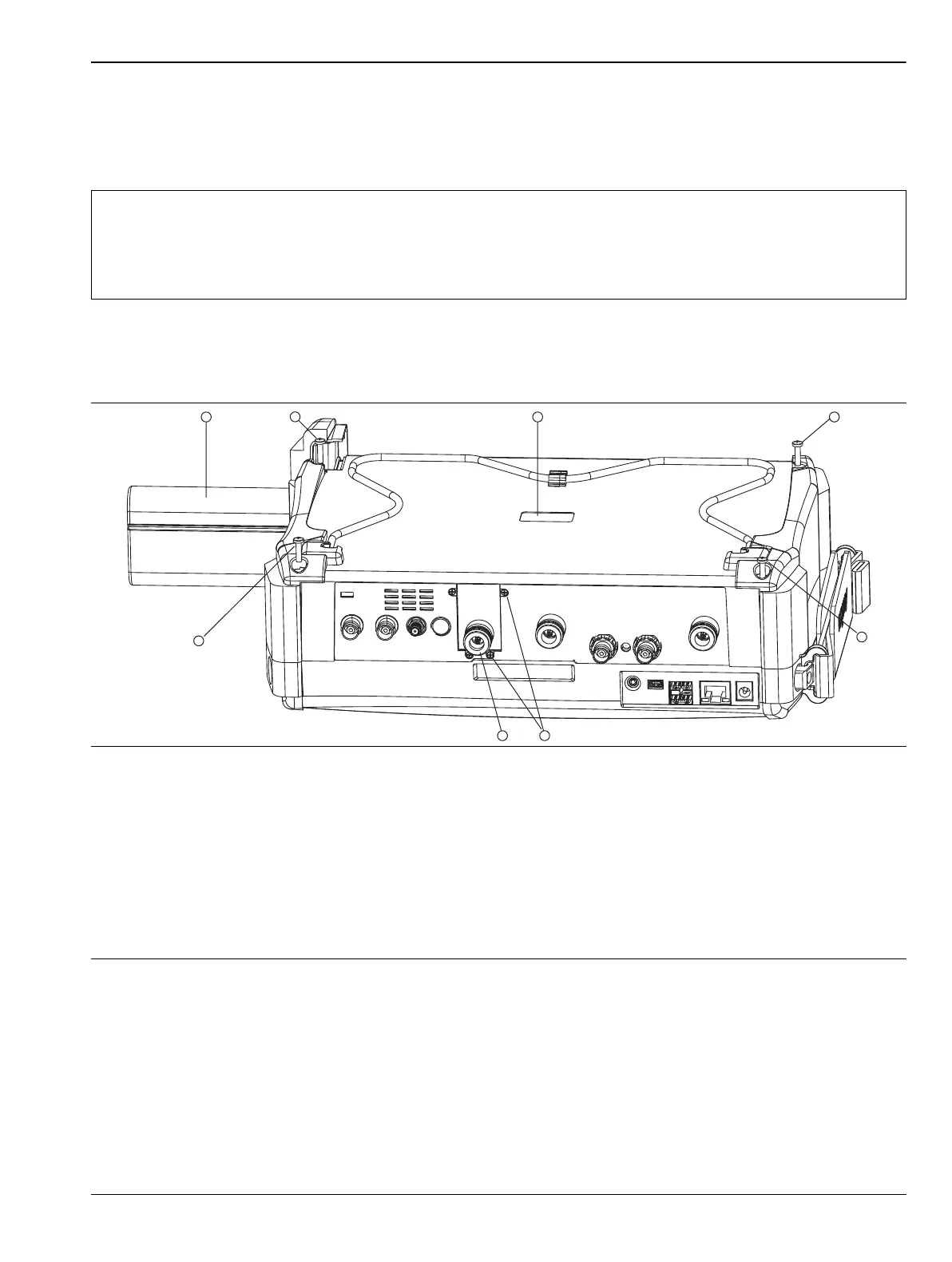
1. Battery
2. Case Back screw (1 of 4)
3. Recess for serial number label (serial number of SPA PCB)
4. Case Back screw (1 of 4)
5. Case Back screw (1 of 4)
6. Screws (4) to hold SPA RF In connector mounting plate to top connector panel
7. SPA RF In port (supplied with SPA PCB)
8. Case Back screw (1 of 4)
Figure 7-40. Case for MS203xC

 Loading...


