i2000SR interface module Service Manual
Page 46 of 212 625798100.APS.5.doc
• Locate the i2000SR IM five metal and five plastic
mounting screws and matching spring nuts (See
Figure 19
).
The metal screws are initially installed and for seismic protection
they are replaced during the installation with plastic screws.
NOTE:
There are two grooves along the side of the TMA. These will
hold the mounting spring nuts. Insert the tabs at the end of
the IM into the grooves and secure it to the TMA using
screws.
The spring nuts and screws are shipped attached to the IM
assembly.
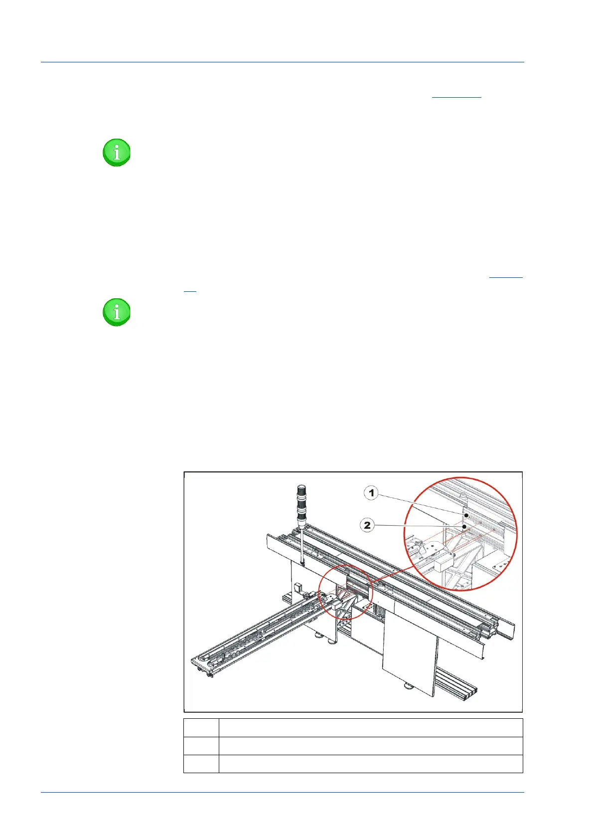
• At the i2000SR IM opening, insert into the upper groove
three (3) square spring nuts and two (2) in the lower. (See
Figure
21
).
NOTE:
At the right end of the IM, the Large Disk is exposed. Use
care to ensure that the disk is not damaged as the i2000SR
IM module is mounted.
• Guide the right end of the i2000SR IM in a manner that
directs the tabs into the groove on the track.
• While holding the IM in position, use the five (5) metal
screws to fasten the i2000SR IM to the TMA. DO NOT tighten the
screws.
Figure 21 – i2000SR IM
No. Description
1 Top groove
2 Bottom groove