Service Manual i2000SR interface module
625798100.APS.5.doc Page 47 of 212
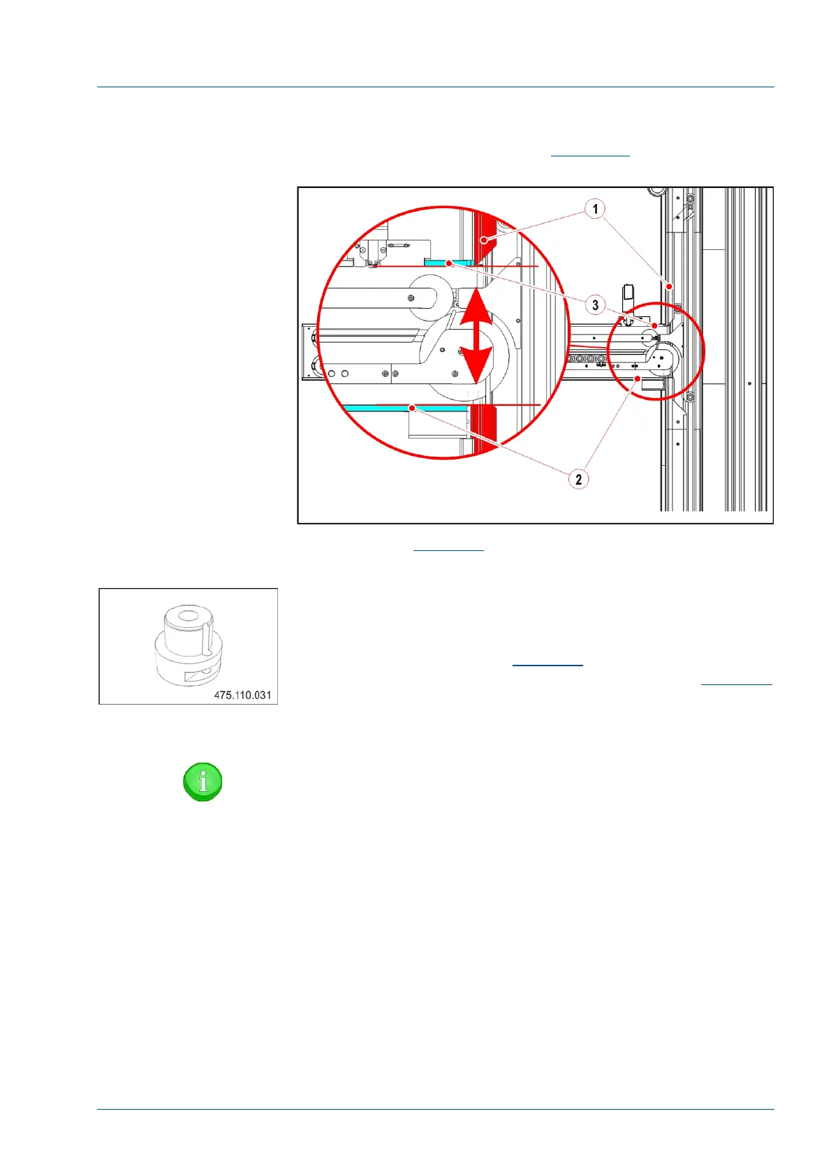
• Using the track opening [1] as a reference, move the IM
extrusion left and right as required to align its extreme edges [2
and 3] to the track opening [1] (See
Figure 23)
Figure 22 – i2000SR IM first alignment
• Refer to
Figure 23
Note that the Disk upper protection [1]
is in alignment with the guide between tracks 1 and 2 [2].
• Use the Oversized Pallet tool (P/N 475.110.031) to verify
that both input and exit lanes are equal in width and that the
carrier template can move freely.
• With reference to the
Figure 18
adjust the position of the
Disk protection until the alignment condition shown in
Figure 23
is verified.
• To secure the position, when the two guides are aligned,
tighten the five (5) screws.
NOTE:
When the Disk upper protection is in alignment with the
Lane 1 / 2 track guides, a carrier is able to move to and
from the track and IM.