PAGE 146
Interfaces
A4.3 Control and data interfaces
A4.3.1 CTRL/DATA/TTL/RELAY interface
This interface is multiple occupied and allows several functions:
– 2 x RS232/RS485 (switchable) for transparent data transmission
– Alternatively, the RS232 can be used for controlling the system
– 6 x TTL input/output, programmable
– 2 x relay output, programmable
The RS232 interface is used to configure and operate the MAGIC DC7/AC1
XIP System with a PC. For a connection to the PC you need a connection ca-
ble, where Pin 2 and Pin 3 are not crossed. Additionally, a Pin 5 GND has to
be connected.
NOTE
Please note that the function - input or output - of the Pins RXD1/2 and
TXD1/2 are determined by the interface type DCE or DTE. The labelling of
the Pin is always RXD for Pin 2 and TXD for Pin 3.
For both data interfaces RXD serves always as receive path and TDX serves
always as transmit path.
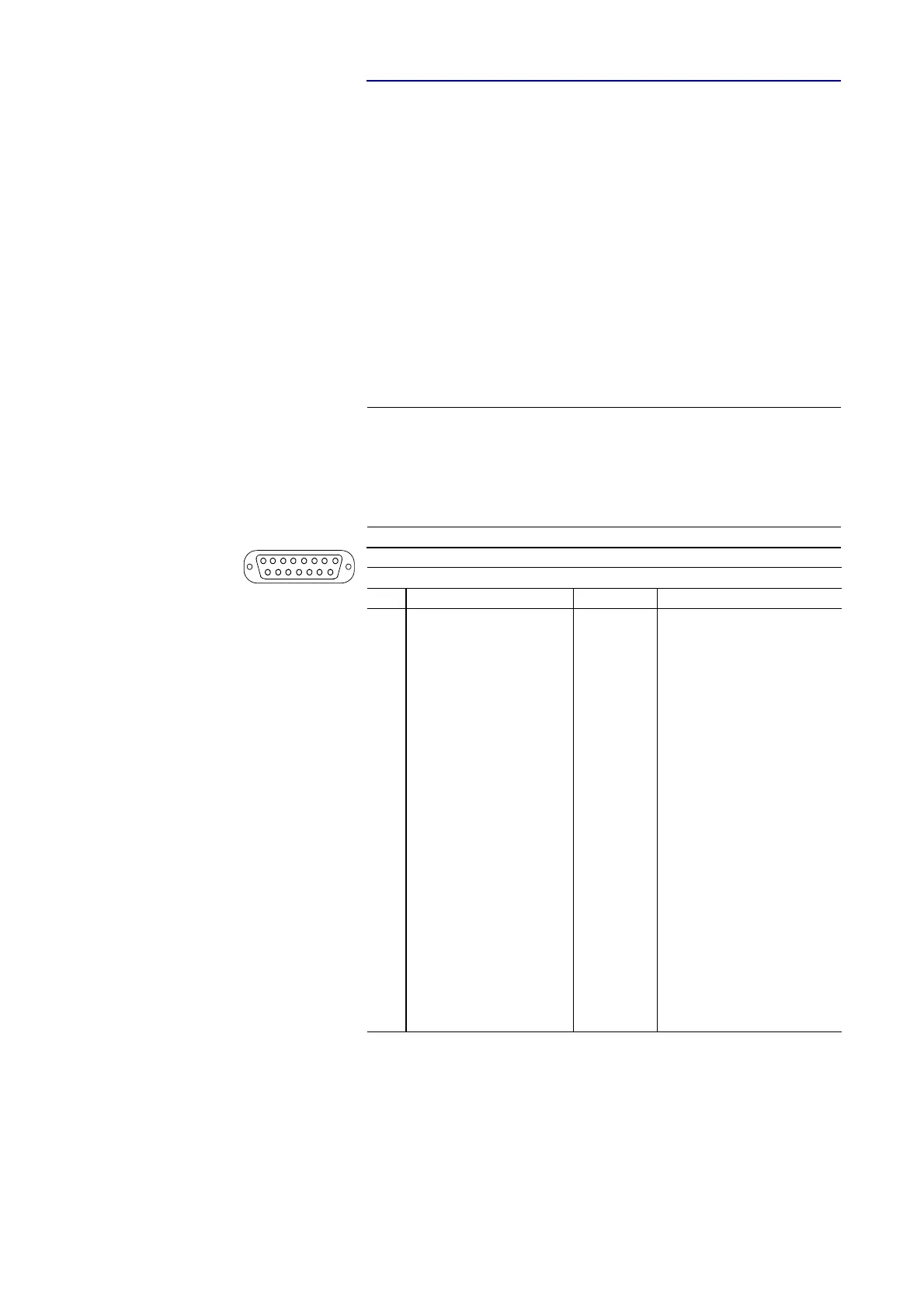
TAB. 11 PIN ASSIGNMENT: CTRL/DATA/TTL/RELAY INTERFACE
Socket: 15-pin SUB-D
Pin Signal Direction Electrical characteristics
1RXD2
a
RS232/RS485 Data (a)
a
ATTENTION: on this Pin the MAGIC DC7/AC1 XIP transmits data
output/E-A
b
b
E-A: input and output at RS485 (bus interface)
PC interfaceRS232:
Type (Pin 2, 3): DCE
c
Level: V.24
Data rate: max. 115200 Baud
Range: max. 15 m
Protocol: 1 start bit
8 data bit
1 stop bit
RS232/RS485 data interface:
Level: V.24 (RS232)
V.11 (RS485)
Data rate: max. 115200 Baud
Range: max 15m (RS232)
max. 100 m (RS485)
Protocol: 1 start bit
8 data bit
1/2 stop bit
Parity adjustable
TTL interface:
Capacity of the TTL outputs:
Maximum voltage: 5V
Maximum current: 10mA
Relay interface:
Capacity of the relays:
Maximum voltage: 48V
Maximum current: 200mA
c
DCE = Data Communication Equipment
2RXD1
a
RS232/RS485 Data (a) output/E-A
b
3TXD1
d
RS232/RS485 Data (b)
d
ATTENTION: on this Pin the MAGIC DC7/AC1 XIP receives data
input/E-A
b
4TXD2
d
RS232/RS485 Data (b) input/E-A
b
5GND
6 RELAY 1 (A) output
7 RELAY 1 (B) output
8 RELAY 2 (A) output
9 TTL1 input/output
10 TTL2 input/output
11 TTL3 input/output
12 TTL4 input/output
13 TTL5 input/output
14 TTL6 input/output
15 RELAY 2 (B) output
18
915