PAGE 98
Windows PC Software
4.9 Menu Extras
4.9.1 Submenu System Monitor
Via the menu System Monitor you receive all information about the status of
the system.
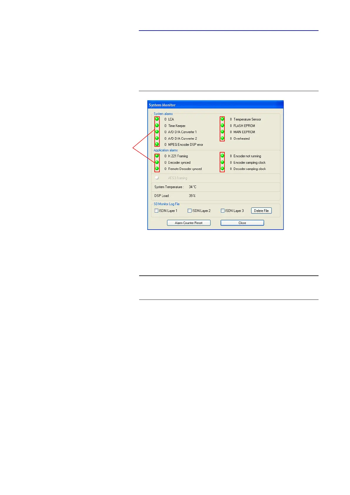
FIG. 75 SUBMENU SYSTEM MONITOR
•Under System alarms all possible system alarms are displayed. A red
LED signals a currently existing alarm. It is also displayed how often the
alarm occured since the unit has been switched on. You can reset the alarm
counter by pressing the Alarm Counter Reset button.
The following alarms are signalled:
– LCA (Logic Cell Array): The communication with a programmed com-
ponent is faulty.
– TIME KEEPER: The communication with the integrated time keeper is
faulty.
– A/D D/A Converter 1: The communication with the first AD/DA con-
verter is faulty.
– A/D D/A Converter 2: The communication with the second AD/DA
converter is faulty.
– MPEG Encoder DSP error: The communication with the DSP module
is faulty (only MAGIC AC1).
– Temperature Sensor: The communication with the temperature sen-
sor is faulty.
– FLASH EPROM: The communication with the non-volantine memory
is faulty. Settings cannot be stored or read.
– MAIN EEPROM: The communication with the non-volantine memory
is faulty. Settings cannot be stored or read.
NOTE
If an alarm occurs several times or for a longer period of time, please discon-
nect the system from electricity. If you switch on the unit and the alarm oc-
curs again, there is probably a hardware defect.
alarm counter