PAGE 151
Interfaces
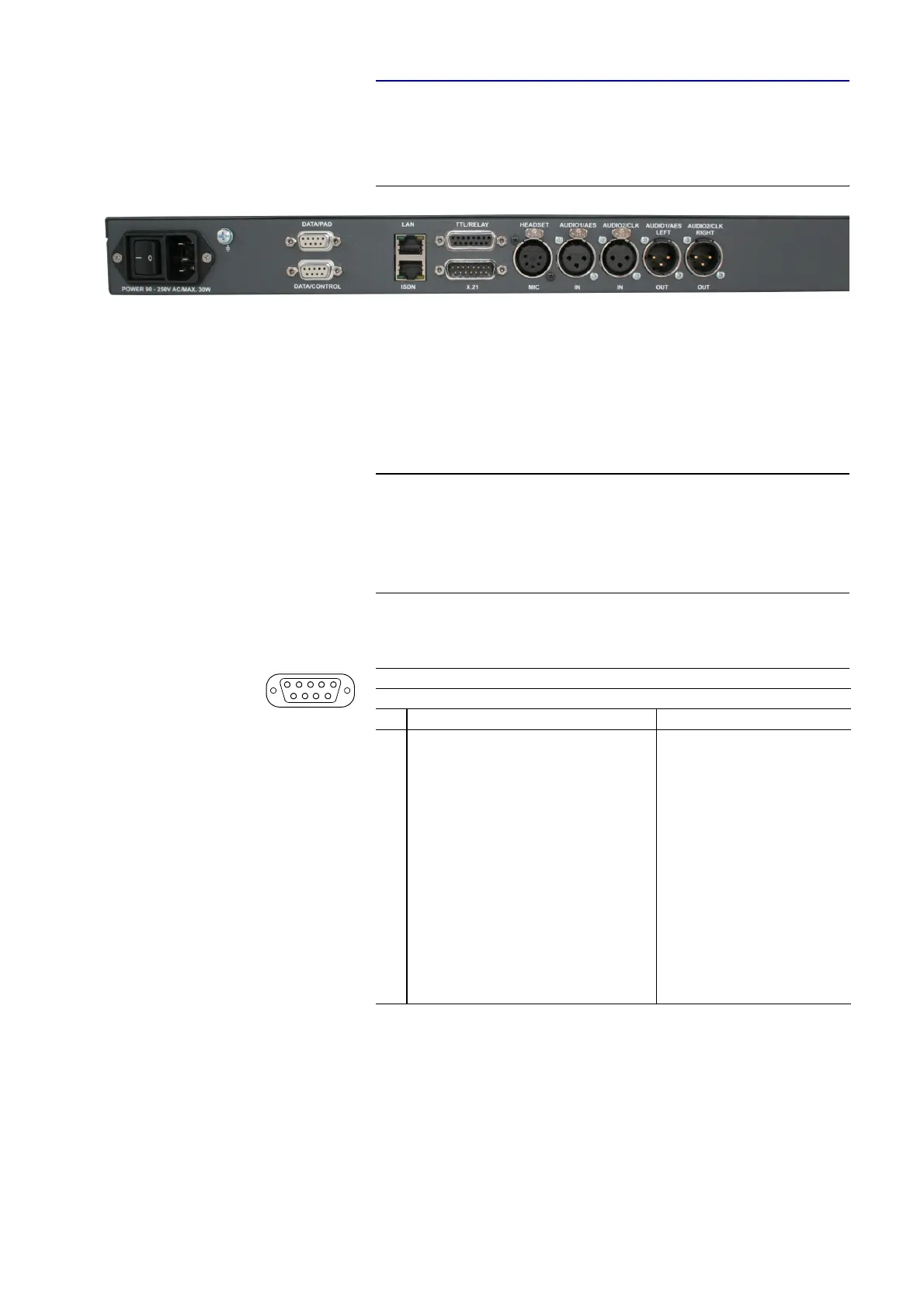
A4.7 MAGIC DC7/AC1 XIP RM
Additionally, for the RM version the CTRL/DATA/TTL/RELAY interface
(see TAB. 11) is splitted. All other interface functions are identical.
FIG. 94 REAR VIEW MAGIC DC7/AC1 XIP RM AUDIO CODEC
A4.7.1 DATA/CONTROL & DATA/PAD interface
The DATA/CONTROL interface can be used either as control interface to the
PC (RS232) or as transparent data interface (RS232/RS485, switchable).
To connect a PC, a 1:1 connection cable is required, where Pin 2 and Pin 3 are
not crossed. Additionally, Pin 5 has to be connected.
The DATA/PAD interface can be used as transparent RS232/RS485 data in-
terface (switchable) only.
NOTE
Please note that the function - input or output - of the Pins RXD1/2 and
TXD1/2 are determined by the interface type DCE or DTE. The labelling of
the Pin is always RXD for Pin 2 and TXD for Pin 3.
For both data interfaces RXD serves always as receive path and TDX serves
always as transmit path.
TAB. 20 PIN ASSIGNMENT: DATA/CONTROL & DATA/PAD INTERFACE
Socket: 9-pin SUB-D
Pin Signal Electrical characteristics
1not used PC interface RS232:
Type (Pin 2, 3): DCE
a
Level: V.24
Data rate: max. 115200 Baud
Range: max. 15 m
Protocol: 1 start bit
8 data bit
1 stop bit
RS232/RS485 data interface:
Level: V.24 (RS232)
V.11 (RS485)
Data rate: max. 115200 Baud
Range: max 15m (RS232)
max. 100 m (RS485)
Protocol: 1 start bit
8 data bit
1/2 stop bit
Parity adjustable
a
DCE = Data Communication Equipment
2RXD1
b
RS232/RS485 Data (a)
b
ATTENTION: on this Pin the MAGIC DC7/AC1 XIP transmits data
3TXD1
c
RS232/RS485 Data (b)
c
ATTENTION: on this Pin the MAGIC DC7/AC1 XIP receives data
4not used
5GND
6not used
7not used
8not used
9not used
5
1
9
6