16 BD High Throughput Sampler User’s Guide
Components
See Figure 1-2 on this page, Figure 1-3 on page 17, and Figure 1-4 on page 18 to
familiarize yourself with the specific HTS hardware components for your
cytometer. For a description of HTS cytometer connections, see Cytometer
Connections on page 19.
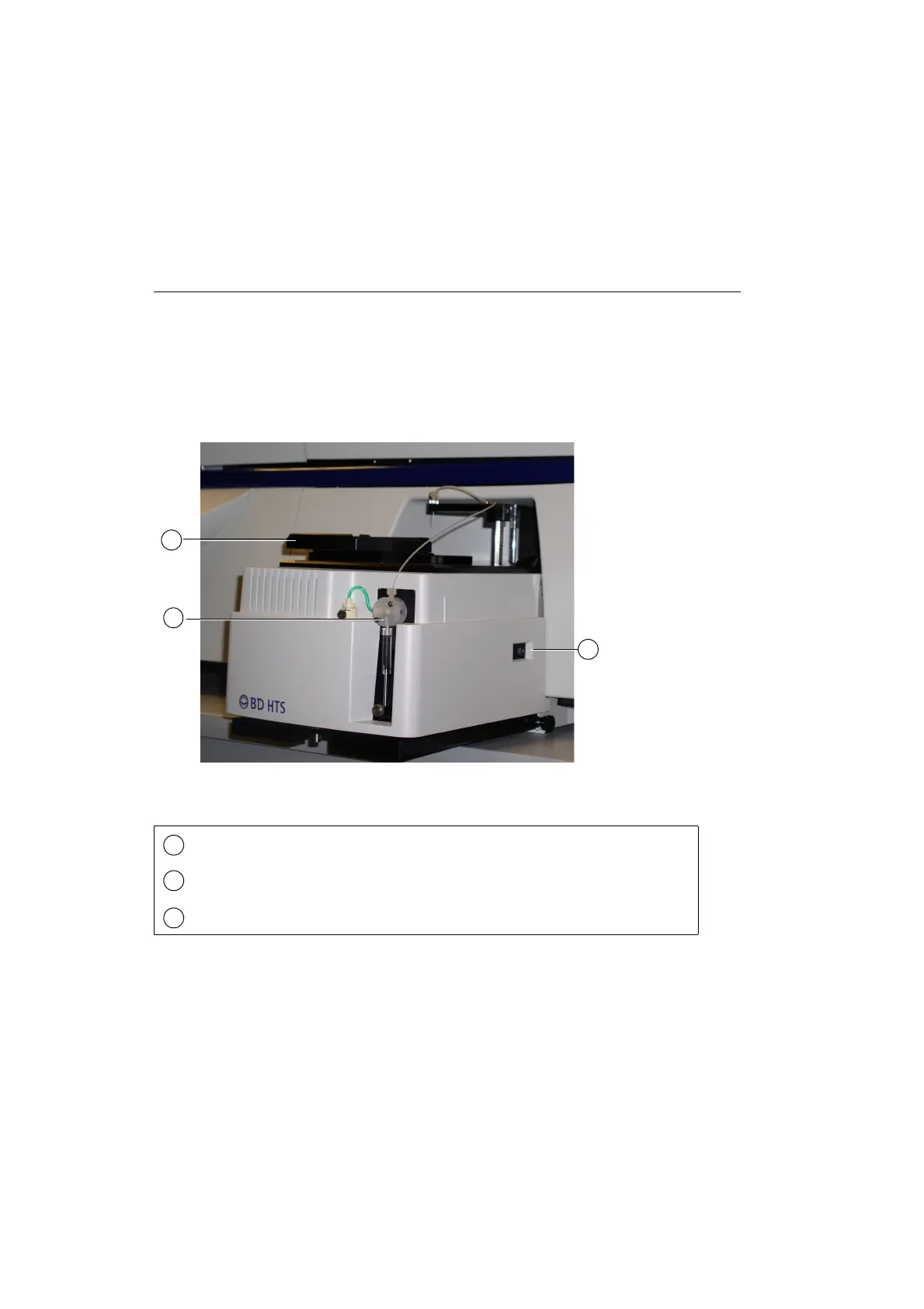
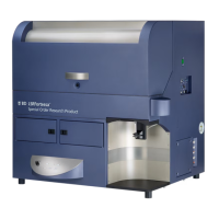
Figure 1-2 HTS unit—front view (example of HTS)
Plate holder—moves left to right and front to back to position plate so the probe can pick up sample
Primary pump and valve—enables mixing and aspiration of sample; delivers sample to flow cell in
standard mode
Power switch and LED indicator for HTS unit
2
3
1
1
2
3