Chapter 1: Introduction 17
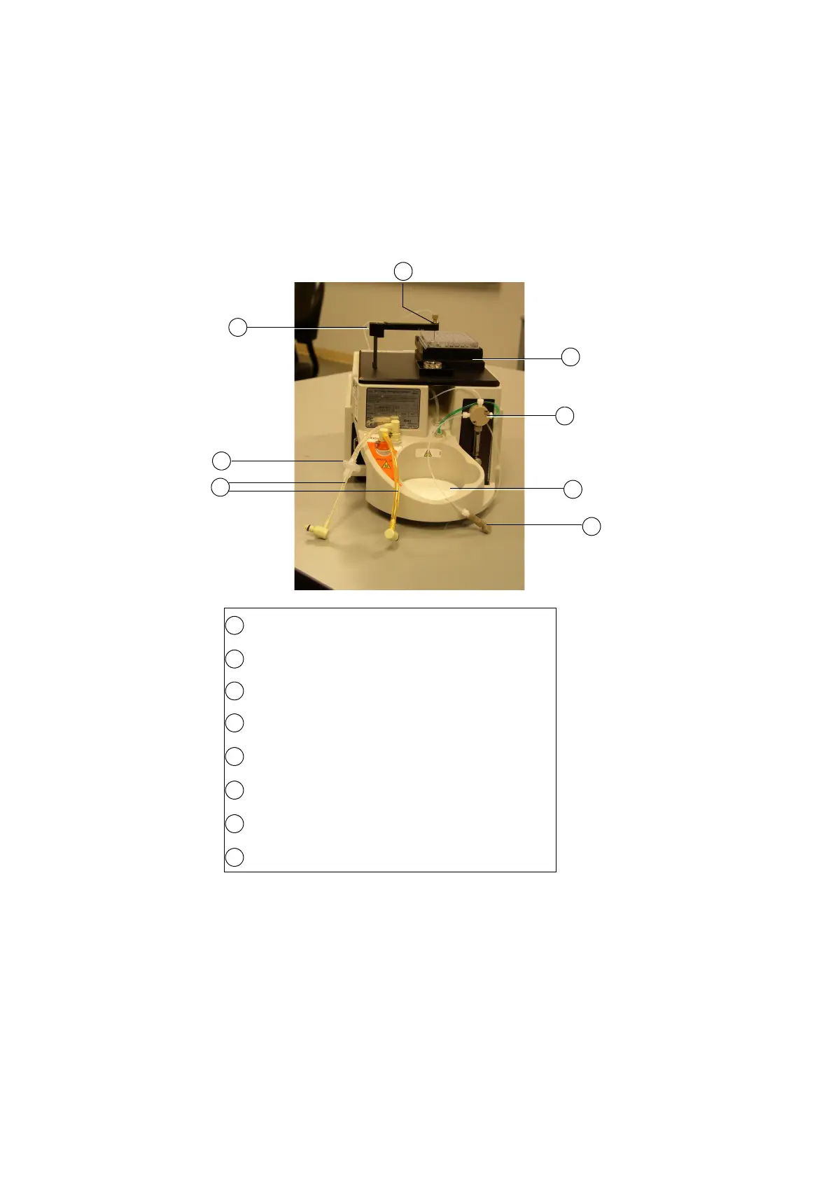
Figure 1-3 HTS unit for BD LSR II and BD FACSCanto—rear view
1
Probe assembly—moves front to back and up and down to transfer
sample between plate holder and injection port/wash station
Fluidics tubing: sheath (clear) and waste (orange)
Sheath filter—filters incoming sheath fluid to HTS unit
Injection port/wash station—provides interface for sample injection
and probe washing
Plate holder—moves left to right and front to back to position plate
so the probe can pick up sample
Secondary pump and valve—delivers sample to flow cell in high-
throughput mode
Absorbent pad—collects potential overflow from the injection port/
wash station or drips from the cytometer sample injection tube (SIT)
Sample coupler—connector between HTS unit to cytometer SIT
1
2
3
4
5
6
7
8
5
6
7
2
8
3
4