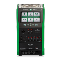
20 - General description
Legend:
1. Temperature Block. See also Figure 3: MC6-T, top view.
2. Display and Touch Panel.
3. Home button. Press this button to return to Home View.
4. Hot Temperature warning symbol that lights up when the
Temperature Block is hot.
5. Process Calibrator Power button, see chapter Power Management.
6. Arrow buttons. First press displays the Hardware Focus Indicator.
Further presses move the indicator on the Display.
7. Enter button for selecting the item surrounded with the Hardware
Focus Indicator.
8. RTD and Resistor connector (R2).
9. RTD and Resistor connector (R3).
10. Voltage, Frequency and Switch input (IN).
11.
Current Measurement, Loop Supply, HART
®
and Fieldbus
connection (IN).
12. Voltage, Current and Frequency output (OUT).
13. RTD and Resistor connector (R1).
14. Thermocouple connectors (TC1 and TC2). TC1 for cables and
standard TC plugs and TC2 for TC plugs with flat contacts.
15. Mains switch (115 V / 230 V). For more details see Power
Management.
16. Mains Inlet socket (115 V / 230 V) to connect the Mains cord.
17. Fuse holders.
18. External Pressure Module connector.
19. Internal Barometric Pressure Module (optional).
20. Ethernet connector.
21. USB-B connector.
22. USB-A connector.