Generations/Simulations - 55
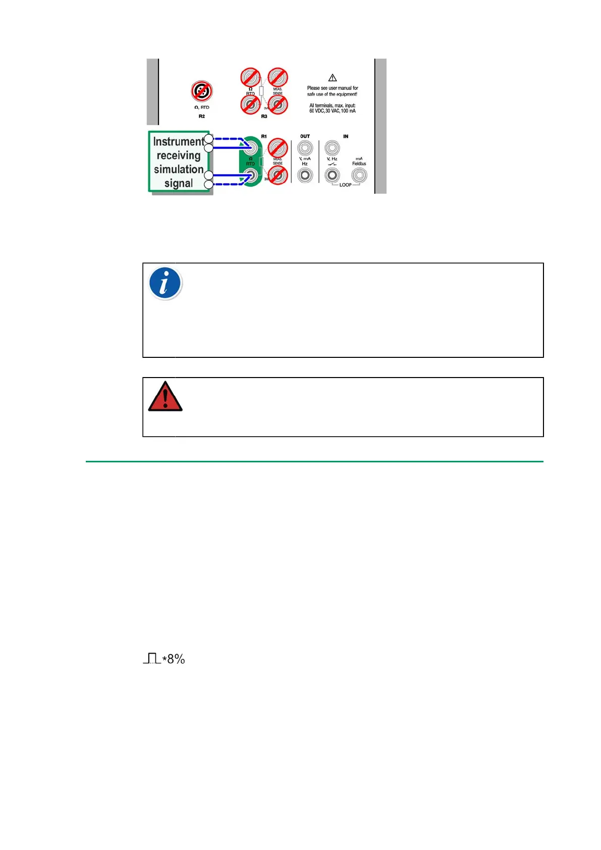
Figure 41: Resistance simulation terminals. Range 0 … 4000 Ohm
See also Resistance Measurement and RTD Sensor Simulation.
Note: When simulating resistance or an RTD sensor, using R1
port, MC6-T does not support measuring the simulated signal
using R2 port.
To ensure good contact between the device under test and the
test leads, we recommend using the alligator clips provided with
MC6-T.
Warning: AC measurement current from the instrument
under test is not supported. With pulsed measurement current,
set a wait time of a few milliseconds before the resistance is
measured.
Frequency Generation
Before generating frequencies, the following settings should be checked:
• Amplitude. Defined from the button with the "V" value.
• Waveform and Duty Cycle. Set together from the rightmost button.
Duty Cycle is the ratio of the output high time to the total cycle time. Due
to technical reasons, the entered Duty Cycle is not always realized with
relatively high frequencies. When the realized Duty Cycle differs from the
desired Duty Cycle, the realized Duty Cycle is shown with an asterisk (*) in
front of it, e.g.: