68 - Temperature Calibrator
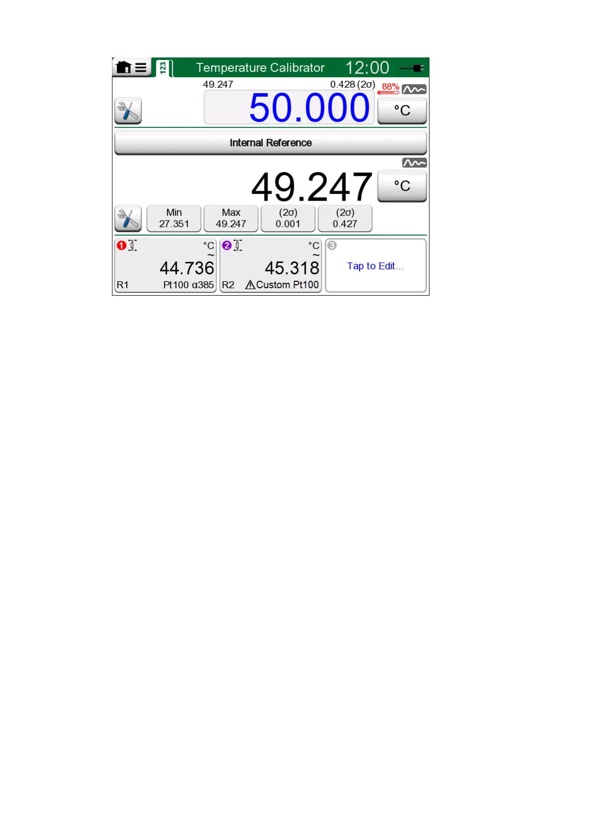
Figure 51: Temperature Calibrator, main view
The three parts of Temperature Calibrator's main view (separated by green
horizontal bars):
1. The upper part is for entering the Temperature Block's set point.
• The small number above the set point and on the left is the internal
reference sensor's temperature.
• The small number above the set point and on the right is the
internal reference sensor's temperature measurement's stability
(2σ).
• The red "thermometer" and a percentage value indicates that
currently MC6-T is heating with 88 % power. If the "thermometer" is
blue, MC6-T is cooling the Temperature Block.
• The tools button on the bottom left is described in chapter Tools.
2. The middle part is for selecting the reference sensor and viewing the
temperature:
• The button on top of the subwindow is for selecting what is used
as reference sensor. The available options are: the internal
reference sensor or any sensor connected to RTD or thermocouple
connected to MC6-T. If the internal reference sensor is not used,
place the external reference sensor in the Temperature Block's
insert.
• Use the Tools button to select which additional information is
shown in the lower part of the subwindow. Stability reading (2σ) and
unstable indicator are recommended to be viewed. They indicate
when the temperature is stable enough to manually document the
results.
3. The lower part has three channels for configuring instruments to be
calibrated. Tap within the channel's frame to select quantity, port/
function etc. Any available function can be selected, selection is not
limited to temperature quantities.