18
Service manual
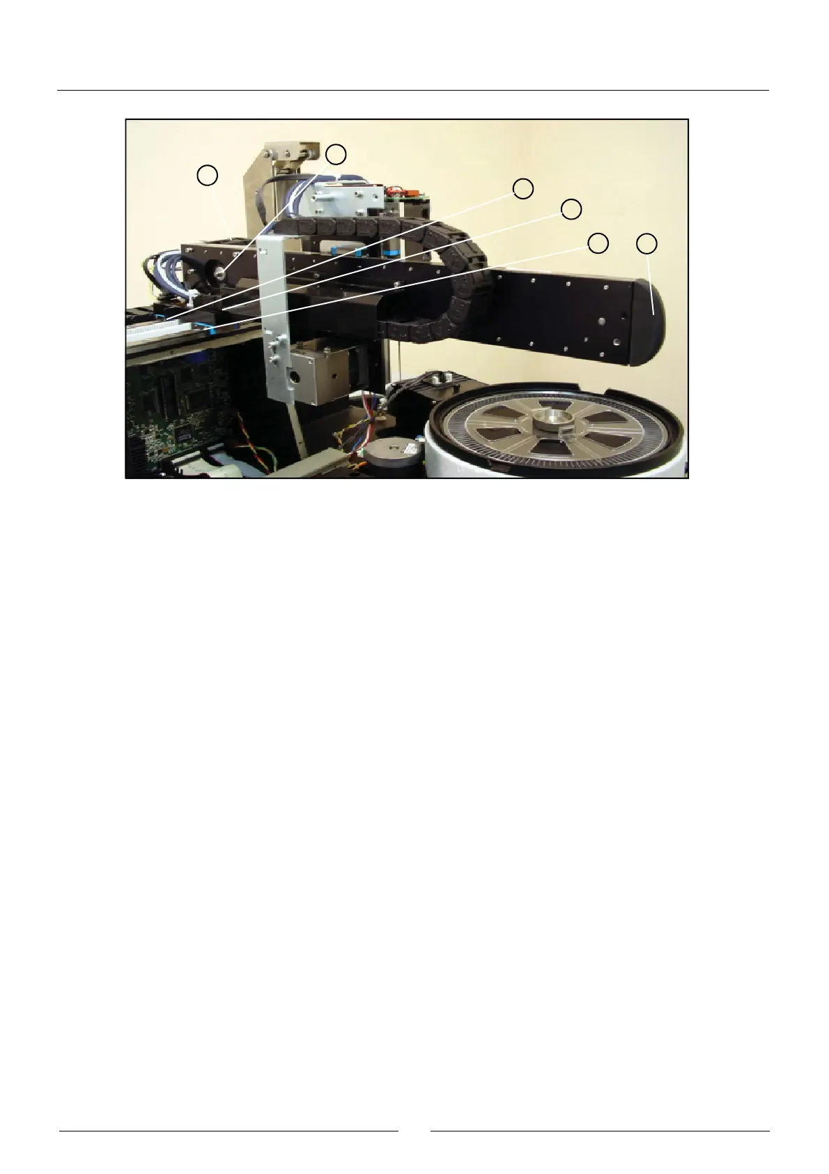
The X carriage can run over the X guide. The body of the X carriage (1) supports the aluminium profile (2) that holds the
steel rails (3) on which the Y carriage runs. The photodetector (4) indicates the start position of the movement of the Y
carriage. The motor (12) operates the Y carriage belt by means of the pulley (11). The pulley (9), fitted on the bearing (10),
returns the belt operated by the motor. The barrier (5) obstructs the X start photodetector when the X carriage reaches its
start position. The X carriage runs on its guide using the linear slide unit (6) fastened to the carriage body. The belt (7)
operates the X carriage. It is held to the body of the X carriage by means of the fastening (8). The support (13) holds the
terminal of the X carriage chain (14). The Y carriage chain terminal (15) is screwed directly onto the X carriage. The rubber
protection (16) prevents the Y guide from injuring the user.
2.2.1.3. Y carriage
(1) Z GUIDE PROFILE
(2) Z TRACK RAILS
(3) Y START DETECTION BARRIER
(4) Z START DETECTION BARRIER
(5) LINEAR SLIDE UNIT
(6) Y CARRIAGE CHAIN TERMINAL
(7) Z CARRIAGE CHAIN TERMINAL
(8) NOTCHED BELT
(9) BELT FASTENING
(10) RETURN PULLEY
(11) BEARING
(12) OPERATING PULLEY
(13) Y CARRIAGE CHAIN SUPPORT COVER
(14) ENCODER PHOTODETECTOR
(15) ENCODER
(16) SPRING
(17) SPRING FASTENING
(18) SUPPORT BODY
(19) COVER
(20) BONDING STRIP
(21) UNIT HOLDING
(22) Z MOTOR
17
6
15
5
11
14