49
Connector Function Pins
J1 LED board connection (CIIM000011) 1 - Vdc
2 - GND
3 - Tx0
4 - GND
5 - Rx0
6 - GND
7 - GND
8 - Tx1
9 - GND
10 - Rx1
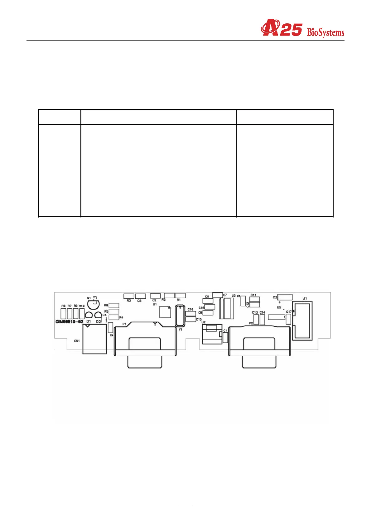
3.7 Communications Board (CIIM00019)
This enables communication with the exterior of the analyzer through a USB channel or a RS232 channel. It also
includes an auxiliary RS232 channel for monitoring the functions of the analyzer during its execution.
CN1 - USB Connector
P1 - Main RS232 connector
P2 - Auxiliary RS232 connector
D1 - USB TX LED indicator
D2 - USB Rx LED indicator
3.8 Interconnection between boards
The following diagrams show the connections between the boards and the different components that make up the
analyzer.