25
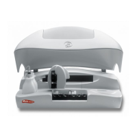
The Teflon tube (4) connects the distilled water container (1) to the electrovalve of the dispensing pump. This tube is
installed at the end of the filter container (5). It is connected to the electrovalve of the dispensing pump through the fitting
(6) The PVC tube (7) connects the distilled water container to the diaphragm pump of the washing water. This tube is
installed at the end of the filter container (8). Both water tubes pass through the rubber piece (3) in the lid (2) of the
container, which fastens them in position. The PVC tube (12) connects the waste extraction diaphragm pump to the
waste container (9). The waste container lid (10) has a fast coupling fitting (11) with automatic drip-proof closing when
disconnected. All the tubes pass into the interior of the analyzer through the rubber grommet (13).
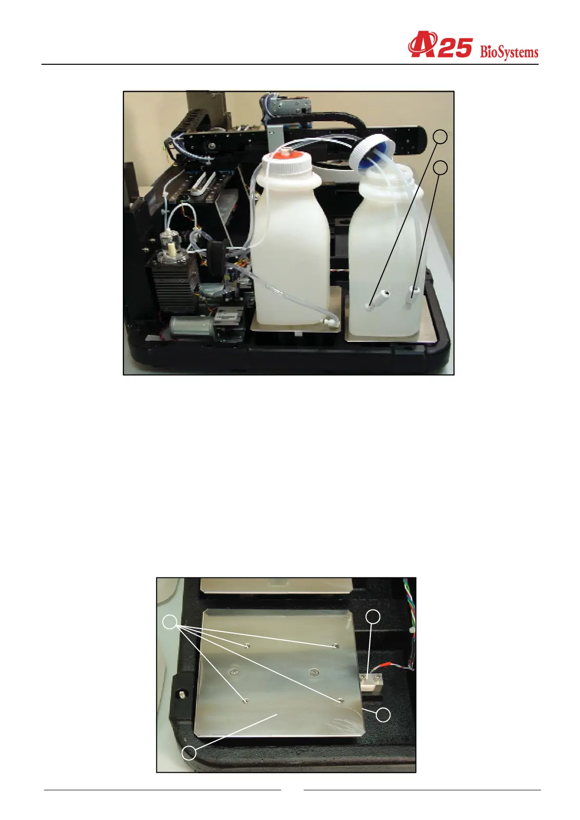
2.2.2.4. Container level control scales
(1) LOAD CELL
(2) BASE SUPPORT
(3) BASE
(4) ADJUSTABLE MAXIMUMS
4
1
2
3
5
8