20
Service manual
The Y carriage can run on the Y guide, which forms part of the X carriage. The aluminium profile (1), which holds the steel
rails (2) on which the Z carriage runs, constitutes the body of the Y carriage itself. The motor (22) operates the Z carriage
belt through the pulley (13). The pulley (11), fitted on the bearing (12), returns the belt operated by the motor.The barrier
(3) obstructs the X start photodetector when the X carriage reaches its start position. The barrier (4) obstructs the Z start
photodetector when the Z carriage reaches its start position. The Y carriage runs on its guide using the linear slide unit
(5) fastened to the carriage body. The belt (9) operates the Y carriage. It is held to the body of the Y carriage by means
of the fastening (10). The support (14) holds the Y and Z carriage chain terminals (7) and the arm housing. The spring-
encoder unit of the Z carriage is made up of components (15)-(22). Part (19) is made up of the system body and contains
the self-raising spring (17) and the encoder (16) for the detection of vertical collisions. Part (18) joins the spring to the
encoder.The photodetector (15) detects the turn of the encoder when it runs along the Z carriage. The cover (20) closes
the system. The motor (23) has two shafts. Its back shaft has the encoder (16) and its front shaft has the operating pulley
of the Z carriage (13). Part (22) holds the system body (19) to the motor. The board (21) joins the system to the
instrument frame.
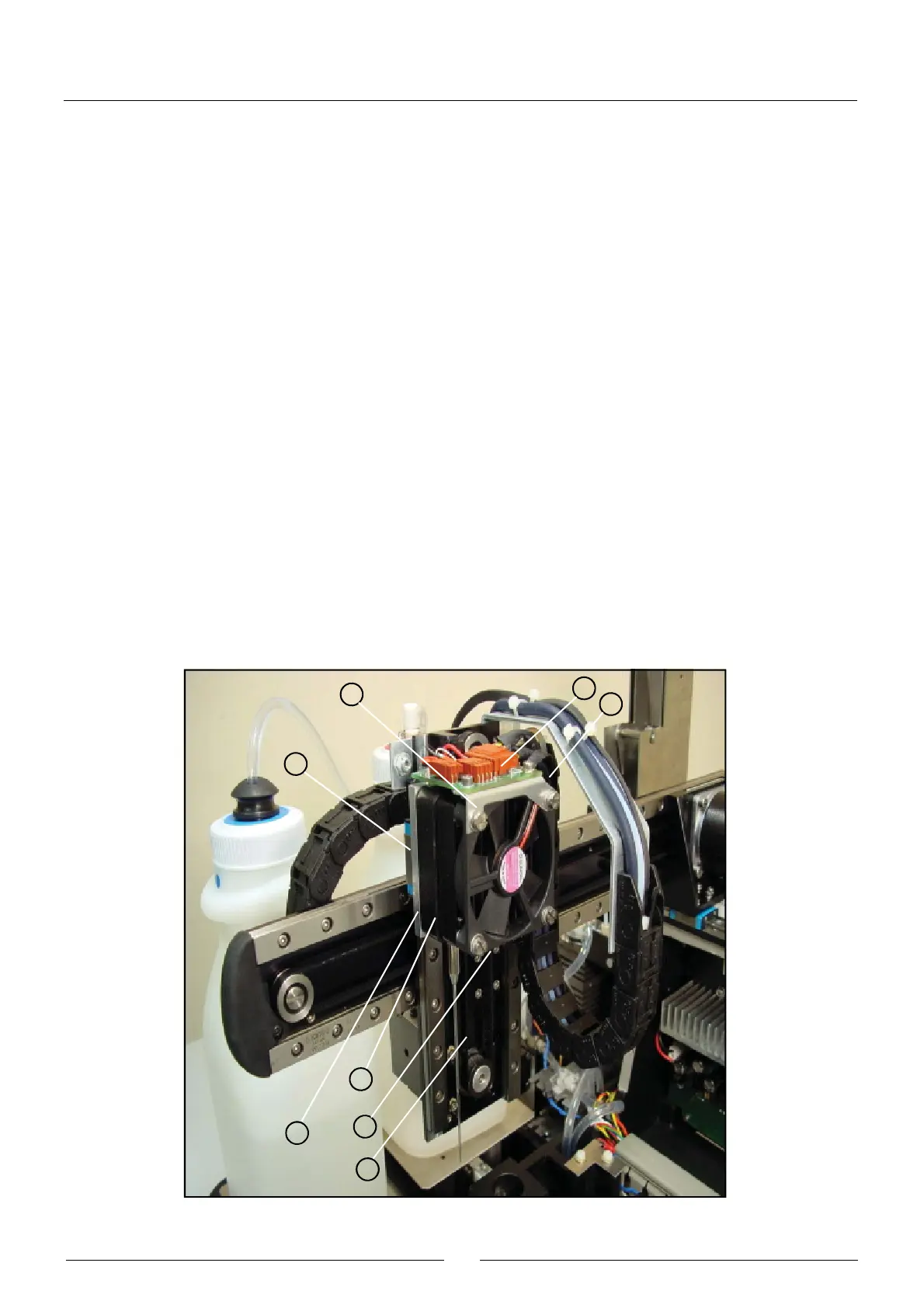
2.2.1.4. Z carriage
(1) ELECTRONIC NEEDLE CONDITIONING BOARD
(2) BOARD SUPPORT
(3) LINEAR SLIDE UNIT
(4) Z CARRIAGE CHAIN TERMINAL
(5) Z CARRIAGE BODY
(6) GEARED BELT
(7) BELT FASTENING
(8) THERMOSTATED NEEDLE
1
4
2
3
5
8
7
6