22
Service manual
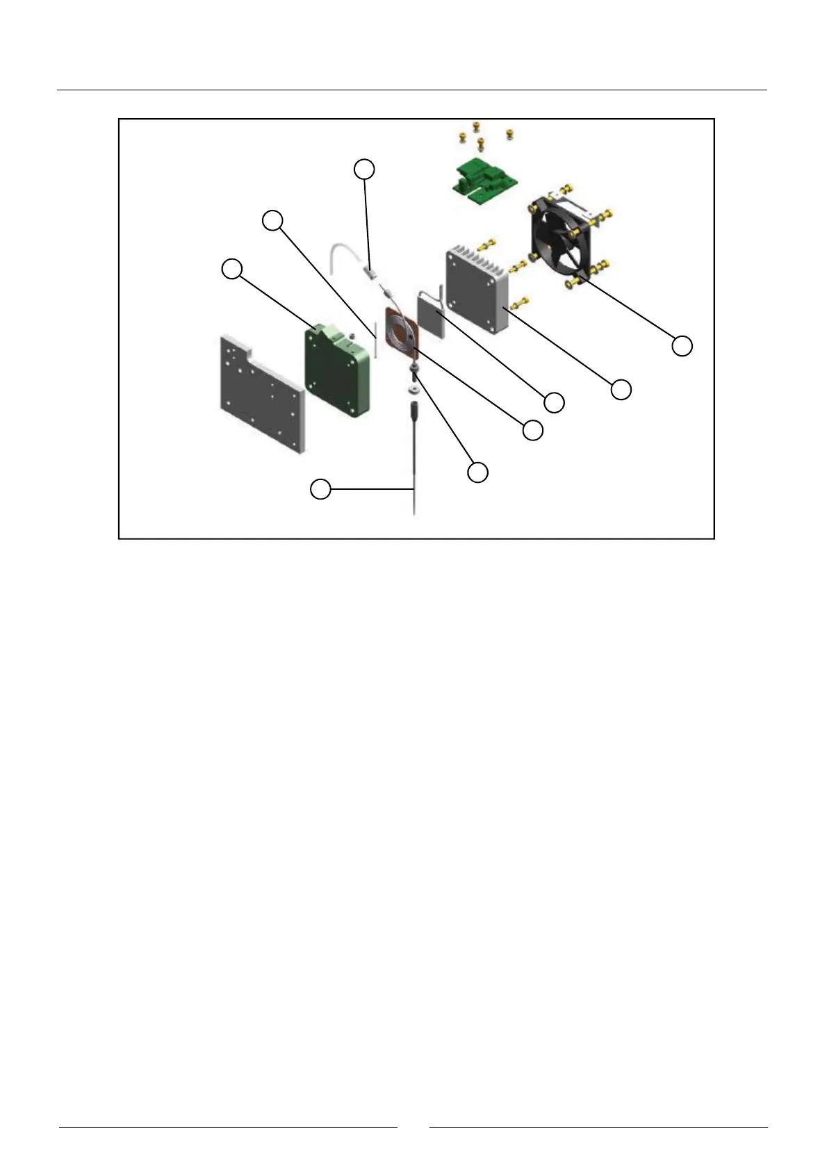
The spiral unit (3) is made up of a spiral tube with fittings at both ends, welded to a copper plate. This unit is housed in
the interior of the plastic body (6). The thermistor (2) is held between these two parts and is the sensor used to control
the system temperature. The lower end of the tube of the spiral unit is firmly fastened to the body by the nut (4). The
removable needle (5) is screwed to this end of the tube. The upper end of the spiral tube is connected to the Teflon
dispensing tube of the operating arm. The fastening fitting (7) ensures said connection. The Peltier cell (1) that controls
the temperature is in contact with the copper plate of the spiral unit. The radiator (8), which is screwed to the plastic body,
closes the system. The bolts that hold the radiator fan (9) are bushing bolts and are used to fasten the entire needle unit
to the Z carriage of the operating arm.
2.2.2.2. Dispensing pump
(1) BODY
(2) FLUIDIC CHAMBER
(3) SEAL
(4) SEAL SUPPORT
(5) CERAMIC PISTON
(6) PISTON SUPPORT
(7) TRANSMISSION PROTECTOR
(8) START DETECTION BARRIER
(9) WORM
(10) AXIAL BEARING
(11) MOTOR
(12) START PHOTODETECTOR
(13) PUMP SUPPORT
(14) PUMP FITTING
(15) PUMP-ELECTROVALVE TEFLON TUBE
(16) 3-CHANNEL ELECTROVALVE
(17) ELECTROVALVE FITTING
7
2
6
5
4
3
1
8
9