69
low step value for the type of rack and then proceed to the Zmax verification motor test. Indicate the type of rack
and position on the tray. Position the rack with the bottles and the primary or paediatric wells, as applicable.
Perform the test and check whether the needle is far from or collides with the bottom. As necessary, return to
the Zmax adjustment menu and increase or decrease the step value on the offset that corresponds to the rack
type. Remember that if the needle collides with the bottom during the test, it retreats a few steps since encoder
detection is not enabled.
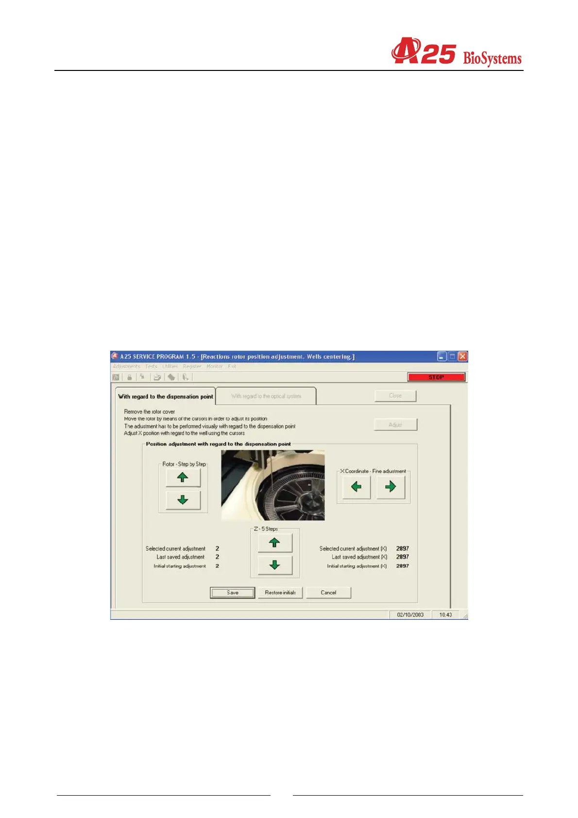
4.2.4. Adjustment of the positioning of the rotor
This screen enables the adjustment of the positioning of the rotor with regard to the dispensing point and the
optical system. One or the other is selected by means of two different tabs.
4.2.4.1. Centering of the rotor with regard to the dispensing point
The analyzer initialises the rotor and positions the first rotor well at the currently programd dispensing position.
The technician has buttons to move the rotor step by step to adjust, if necessary, this position and buttons for finer
adjustment of the X coordinate over the dispensing point. At all times, the screen shows the current dispensing
coordinate on the first well and of the X axis position, the last coordinate stored and the initial screen input
coordinate, as additional information for the technician. When this is satisfactory, the current coordinate of the
dispensing point of the first well can be stored by pressing the Store button. Pressing the Cancel button keeps the
last stored value and the current value is not stored. Pressing the Restore button restores the initial screen input
value.
4.2.4.2. Centering of the rotor with regard to the optical system
This adjustment is necessary only if the Rotor Centering Adjustment has been carried out with regard to the
dispensing point (4.1.4.1.). This adjustment must be made with the rotor cover in position. The analyzer initialises
the rotor and fills the first 3 wells of the rotor with distilled water. Next, step-by-step optical readings are made
through these wells at the wavelength selected by the technician. Once the readings have ended, the program
shows a graph of the light intensity measured on the rotor steps. On this graph, the program indicates at which
points the optical readings are made on each of the 3 wells when the analysis is made, with the coordinate of the
reading point of the first well currently programd in the analyzer. If necessary, the technician can move the reading
points over the graph jointly using two buttons. The optimum reading point is that which globally maximises the
light intensity for the three wells. At all times, the screen shows the current coordinate of the reading in the first
well and the last coordinate stored, as additional information for the technician. When the position is satisfactory,