36
Service manual
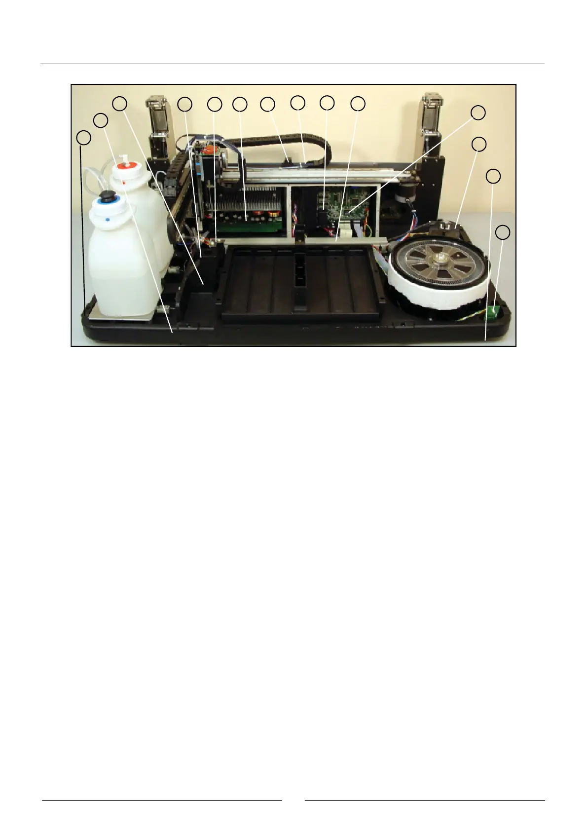
The base (1) on which all the components of the analyzer are fastened is made of cast aluminium, machined and painted.
The plastic channel (2) carries the cable hoses of different components to the electronic boards of the microprocessor
(10) and the power supply (11). The metallic bracket (3) is used by the analyzer to check the state of the needle. The
metallic cover (4) closes the conduit for optional auxiliary devices at the bottom of the base. The support (6) makes it
possible to fasten the ends of the hoses of the operating arm by means of plastic CLAMPs. The terminal of the X carriage
chain (7) is screwed directly to the base. The grill (8) protects the lighting system fan. The metallic covers (9) (removed
to see the boards) close at the front of the electronic boards of the microprocessor and the power supply. The board (12)
contains the front LED indicator of the instrument and is fastened directly to the base. The instrument stands on 4 rubber
legs (14). The front right leg (13) is adjustable in height to adapt the instrument to the work surface.
2.2.7. Housings
(1) FRONT HOUSING
(2) REAR HOUSING
(3) MAIN COVER
(4) COVER WINDOW
(5) ARM HOUSING
(6) OPTICAL SYSTEM COVER
(7) ROTOR COVER
(8) AUXILIARY DEVICES HOUSING COVER
4
53
11 6
79
2
14
1
10
8
13
12