Service manual
102
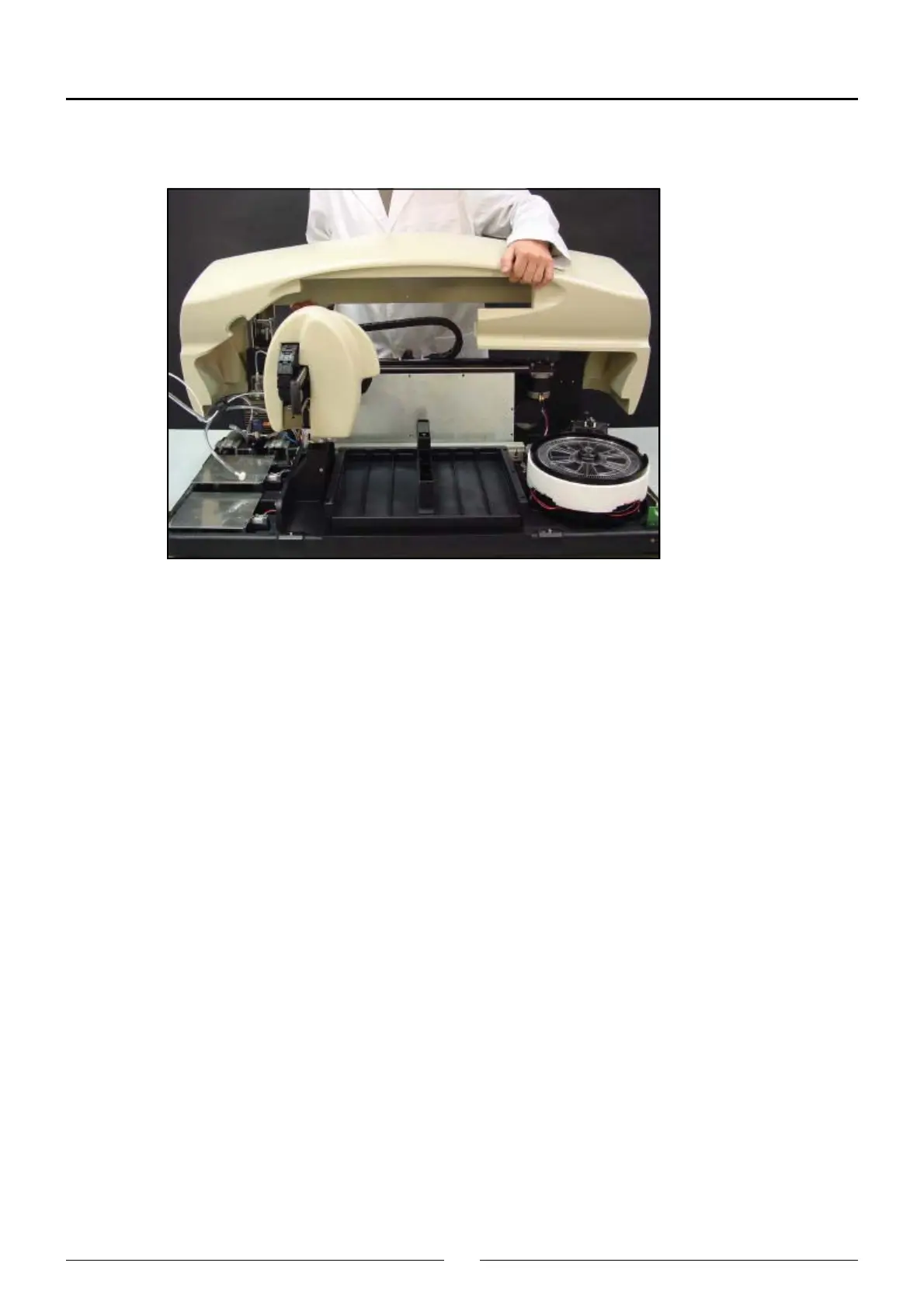
5.1.1.5. Removing the main cover hinges
a) Remove the main cover and the corresponding back metal covers.
b) Disconnect the electrical hose from the cover detector.
c) Remove the 4 screws that hold each hinge to the base. The 2 top screws of each hinge must be removed by
introducing the Allen key in the back holes of the hinges.
5.1.2. Operating arm
5.1.2.1. Fully removing the operating arm
a) Remove all the analyzer housing.
b) Remove the front cover over the electronics.
c) Disconnect all the electrical hoses from the arm.
d) Remove the support of the clamps together with the terminal of the X carriage chain.
e) Take the cables out.
f) Remove the nut on the electrovalve and cut the clamps that hold the tube to the base.
g) Remove the electronic microprocessor and power supply boards.
h) Remove the arm by removing the 12 screws on the X guide.
5.1.2.2. Changing the cable carrier chain with the electrical hoses and dispensing tube
a) Remove all the analyzer housing.
b) Disconnect all the connectors and bonding strips of the electrical hoses from the arm and cut all the necessary
clamps.
c) Disconnect the Teflon dispensing tube at both ends (needle and electrovalve).
d) Remove the support cover from the Y carriage cable carrier chain.
e) Separate the cable carrier chains from their terminals using a small screwdriver as a lever and removing the pins from
the holes that join the chain links together. It is not necessary to remove the terminals from their supports.
f) Remove the cable carrier chain.
g) Install the new chain, make all the connections and replace the cut clamps.