24
Service manual
The aluminium body (1) joins the different components that make up the pump. The transparent methacrylate fluidic
chamber (2) makes it possible to observe the flow of liquid through the pump. The support (4) fastens the seal (3) to the
chamber.The ceramic piston (5) dispenses by displacing a certain volume of liquid in the chamber. The plastic protection
(7) prevents the pump transmission from getting wet if the seal fails. The piston is adhered to the support (6), which
moves alternatively by the rotation of the worm (9) fixed to the motor shaft (11). The barrier (9), joined to the piston
support, obstructs the photodetector (12) when the piston reaches its start position. The axial bearing (10) prevents any
longitudinal displacement of the motor shaft for greater precision in the dispensing operation. The 3-channel electrovalve
(16) makes it possible to connect the pump chamber to the distilled water container or to the thermostated needle. The
support (13) makes it possible to fasten the pump and the electrovalve to the analyzer. The Teflon tube (15) connects the
chamber to the electrovalve. It is connected to each of these components by the fittings (14) and (17).
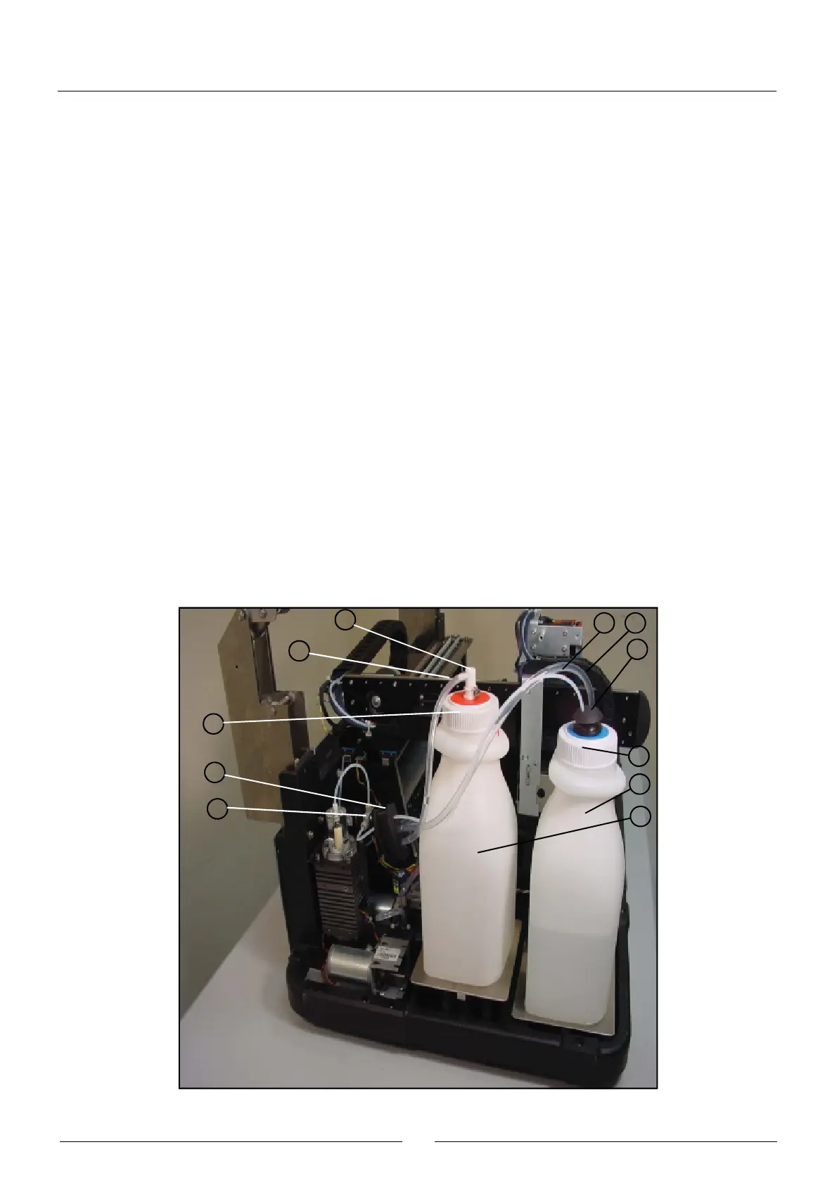
2.2.2.3. Tubes and containers
(1) WATER CONTAINER
(2) WATER CONTAINER LID
(3) WATER CONTAINER TUBES FASTENING
(4) WATER CONTAINER TEFLON TUBE
(5) TEFLON TUBE FILTER
(6) ELECTROVALVE FITTING
(7) WATER CONTAINER PVC TUBE
(8) PVC TUBE FILTER
(9) WASTE CONTAINER
(10) WASTE CONTAINER LID
(11) FAST COUPLING FITTING
(12) WASTE CONTAINER PVC TUBE
(13) GROMMET
12
10
11
13
4 7
3
2
1
9
6