Service manual
48
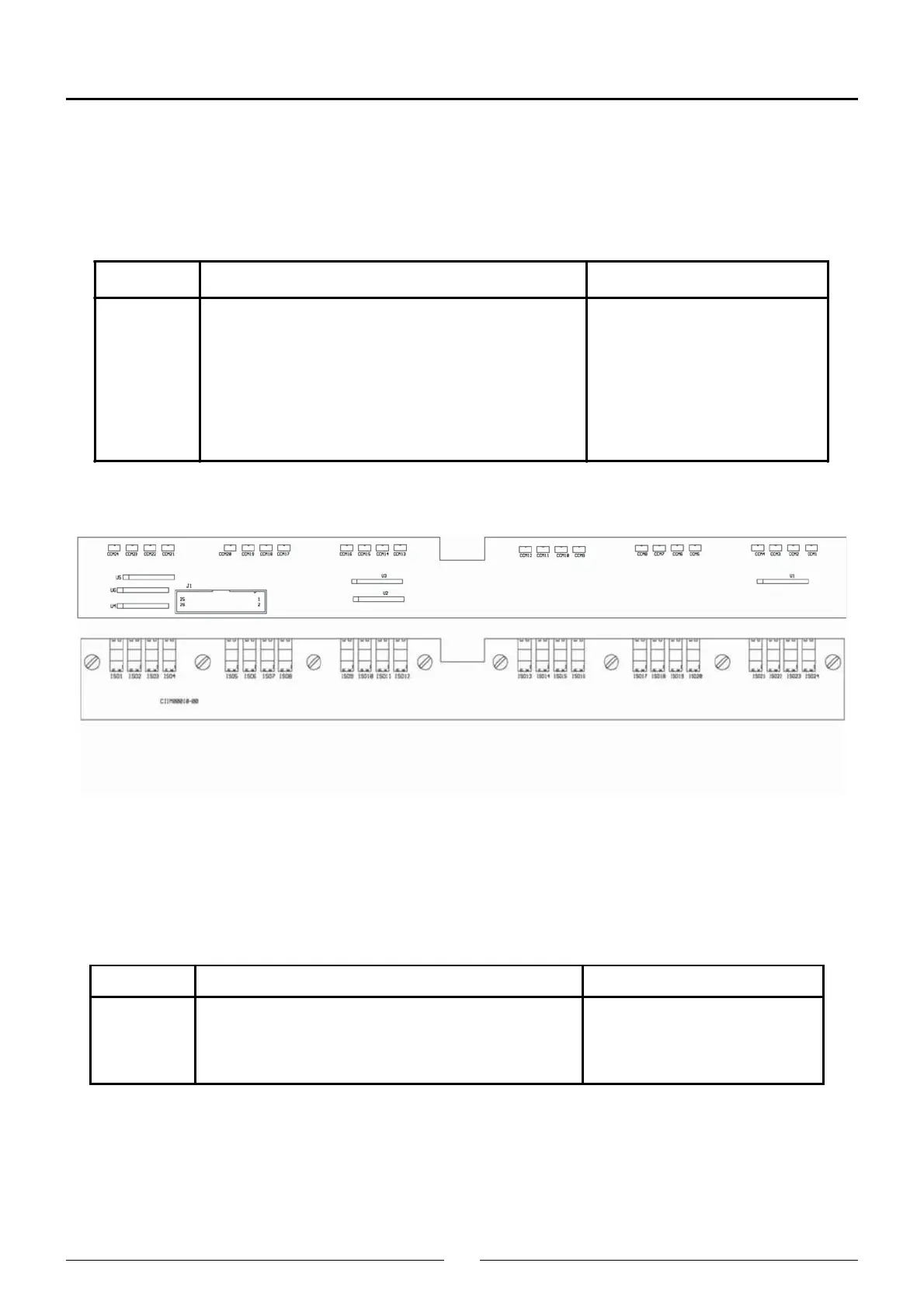
3.5 Racks Board (CIIM00010)
This board decodes the rack type the analyzer has at each of the positions for said racks. It is made up of a battery of
photobarriers that allow or stop light passing through the rack identification tabs at logical levels the analyzer firmware
can handle.
3.6 LED Board (CIIM00011)
This board indicates the different states of the analyzer. It is made up of a bicolor LED and the circuitry associated with
action.
Connector Function Pins
J1 CPU board connection (CIIM00006) 1 - Detector 1
2 - Detector 2
.
.
24 - Detector 24
25 - GND
26 - Vdc
Connector Function Pins
J36 LED board connection (CIIM000011) 1 - GND
2 - LED
3 - LED
4 - Vdc
D1 - Bicolor LED