30
Service manual
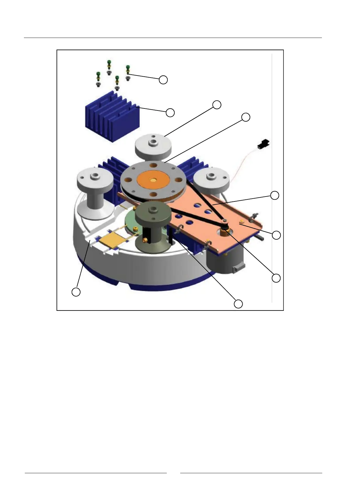
The dispensing system dispenses the reagents and the samples in the methacrylate rotor (1). The optical system
measures the absorbance directly on the rotor wells. The aluminium heating channel (2) surrounds the rotor and keeps
it at 37ºC. The channel is thermally insulated from the exterior by means of the molded expanded polystyrene insulation
(3). The Peltier cells (4), with their respective radiators (5), act on the channel to control the temperature. The screws that
fasten the radiators are thermally insulated from the former by the bushes (6). The sensor used to control the temperature
is the probe (27), which is thermally insulated from the exterior of the channel by means of the sleeve (28). The methacrylate
rotor is fastened to its centerer (8) by means of the screw (7). The centerer is fastened to the rotor (12), which is mounted
on bearings (13) in the gear support (10). This support is screwed to the heating channel. The plastic part (9) thermally
insulates both parts from each other. The barrier obstructing the photodetector (11) when the rotor reaches its start
position forms part of the centerer (8). The pulley (19), fastened to the motor (18), acts, by means of the belt (14), on the
pulley (14) fastened to the rotor. The gear ratio is 1:12. The spacer (17) makes it possible to move the motor on its
support (16) to adjust the belt tension correctly. The electronic board of the photometric system (24) is housed in a cavity
in the heating channel. The upper cover of this cavity (20) supports the electronic board. The seal (21) keeps the cavity
hermetically closed in the case of possible liquid spillage. The cavity is closed at the bottom by the cover (22). The
photodiode is welded onto the board on the spacer (25). The part (23) centers the photodiode with regard to the lighting
system and also acts as a grill to prevent the incidence of unwanted light. The grill (26) limits the light hitting the reactions
rotor. The detector (29) tells the analyzer if the rotor cover is in position or not. The part (30) connects the heating
31
6
5
32
14
15
16
19
4