32
Service manual
(27) FAN
(28) FASTENING BRACKET
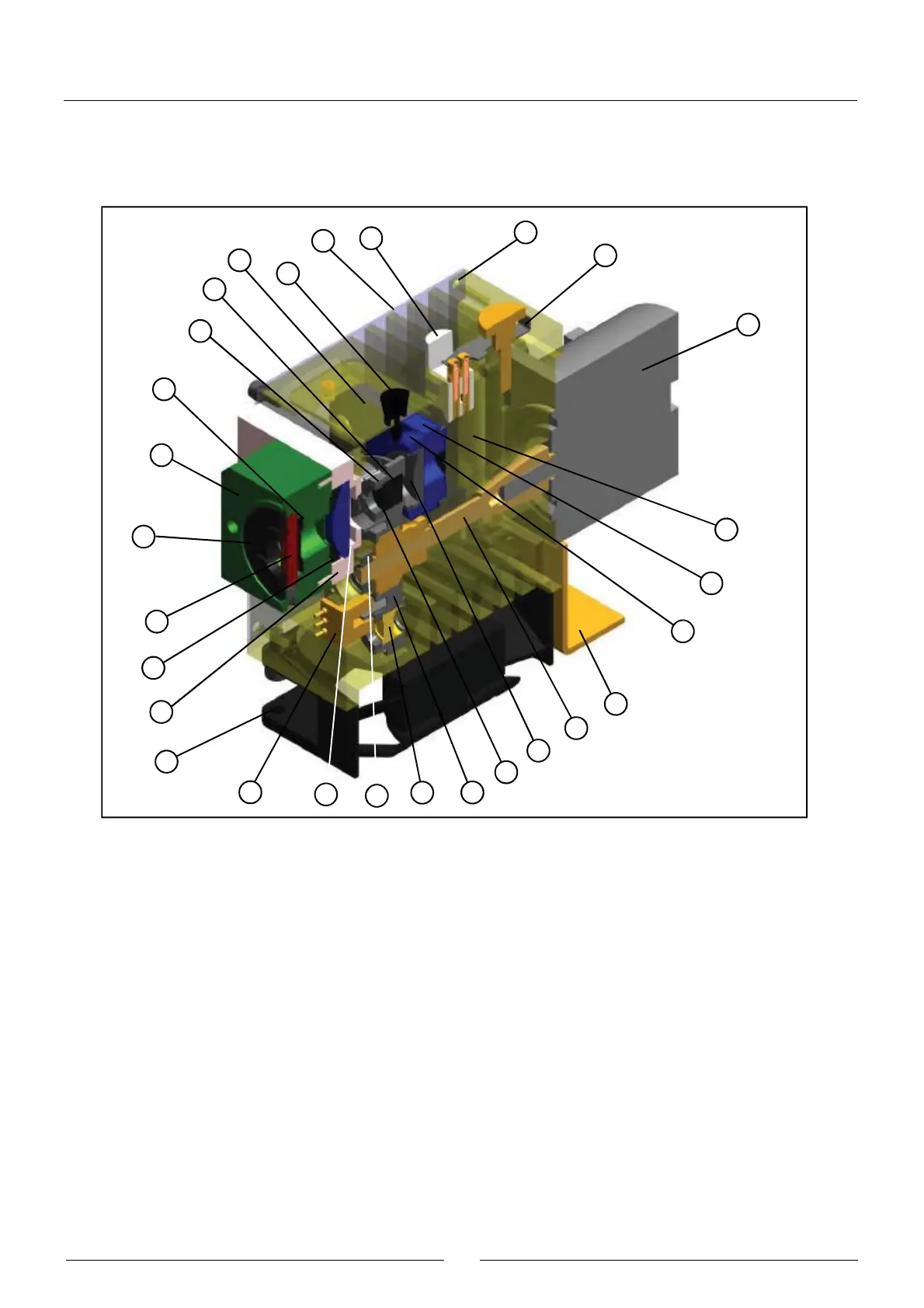
The aluminium body (1) is the structure that supports all the components of the lighting system. The lamp holder (2),
fastened to the body by means of the fastening system (4), keeps the halogen lamp (3) in position without the need for
adjustments. The filter wheel (5) has 10 positions for optical filters. Position 0 must always be taken up by a covered filter
(8). The other positions can be taken up by an interferential filter (9) or by other covered filters. No position in the wheel
must be left unoccupied. Each filter is fitted on a filter holder (6) and fastened to it by the nut (7). The filter holders can be
dismounted from the wheel by simply pulling on them. The cover (25) allows easy access to the filter wheel. The filter
wheel is fastened to the shaft (10). This shaft can be turned by the direct action of the motor (13). Its end is guided by the
bearing (11). The photodetector (12) indicates the start position of the wheel. The light from the lamp, limited by the
diaphragm (15), passes through the collimating lens (16) fastened to its support (14) by the nut (17). The light passes
through the filter wheel, which selects the desired wavelength, and passes through the lenses (19) and (23) and the slot
(22), which adapt the form of the light beam to the geometry of the rotor wells. These lenses are mounted on their
respective supports (18) and (21) and are fastened by parts (20) and (24), respectively. The system body is laterally
closed by the covers (26) and the fan (27) keeps it at a desired temperature. The lighting system is fixed to the rotor and,
by the bracket (28), to the base of the analyzer.
1
4
13
2
26
15
25
8
7
22
21
24
23
20
18
27
12
19
11
9
5
6
16
10
28
17
14
3