Introduction 15
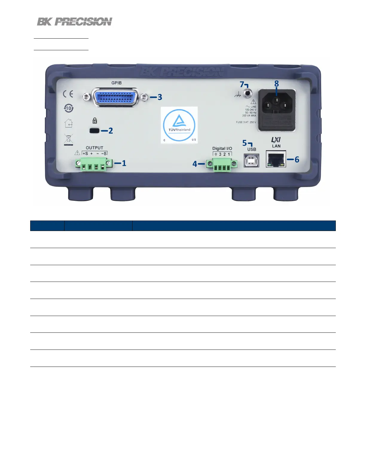
1.8 Rear Panel
Figure 1.5 Rear Panel
Item Name
Description
1 Output/Sense
Rear panel output with remote sense. Internal relays switch between local and
remote sensing.
2 Kensington security slot
Lock the instrument to a xed location using the security lock via the lock hole.
Lock is not included.
3 GPIB Interface (Optional) Connect a GPIB cable to remotely control the unit `
4 Digital I/O Send or receive a signal to or from an external device.
5 USB interface Connect a USB type B to type A to remotely control the unit.
6 LAN interface
Connect a Cat 5/6 Ethernet straight-through patch cable to remotely control
the unit.
7 Chassis ground
Provides a zero potential voltage reference and a dissipation point for interfer-
ence, transient voltages and static.
8
AC power input
& fuse box
Houses the fuse as well as the AC input.
Table 1.4 Rear Panel
 Loading...