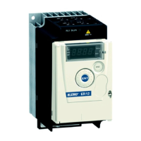
Configuration Mode (ConF)
Code Nam e / De s cription Adjustment range Factory setting
AI1A
nO
AO1
Fr1
Fr2
SA2
PIF
tAA
dA2
PIM
FPI
SA3
dA3
FLOC
MA2
MA3
IA01
...
IA10
[AI1 assignment]
Read-only parameter, cannot be configured.
It displays all the functions associated with input AI1 in order to check, for example, for compatibility problems.
[No]
(nO): Not assigned
[AO1 as s ignm ent]
(AO1): Analog output AO1
[Ref.1 channel]
(Fr1): Reference source 1
[Ref.2 channel]
(Fr2): Reference source 2
[Sum m ing ref. 2]
(SA2): Summing reference 2
[PID fe e dback ]
(PIF): PI feedback (PI control)
[Torque lim itation]
(tAA): Torque limitation: Activation by an analog value
[Subtract. ref. 2]
(dA2): Subtracting reference 2
[M anual PID re f.]
(PIM): Manual speed reference of the PI(D) regulator (auto-man)
[PID spe e d ref.]
(FPI): Speed reference of the PI(D) regulator (predictive reference)
[Sum m ing ref. 3]
(SA3): Summing reference 3
[Ref.1B channel]
(Fr1b):
Reference source 1B
[Subtract. ref. 3]
(dA3): Subtracting reference 3
[Force d local]
(FLOC): Forced local reference source
[Ref.2 m ultiplie r]
(MA2): Multiplying reference 2
[Ref. 3 m ultiplier]
(MA3): Multiplying reference 3
[Weight input]
(PES): Hoisting: External w eight measurement function
[IA01]
(IA01):
Function blocks: Analog Input 01
...
[IA10]
(IA10):
Function blocks: Analog Input 10
AI1t
10U
[AI1 Type]
[Voltage]
(10U)
[Voltage]
(10U): Positive voltage input 0 - 10 V (negative values are interpreted as zero: the input is unidirectional)
UIL1
[AI1 min value]
0 to 10.0 V 0 V
AI1 voltage scaling parameter of 0%.
UIH1
[AI1 max value]
0 to 10.0 V 10.0 V
AI1 voltage scaling parameter of 100%.
AI1F
[AI1 filter]
0 to 10.00 s 0 s
Interference filtering.
AI1L
POS
nEG
[AI1 range]
[0 - 100%]
(POS)
[0 - 100%]
(POS): Positive logical
[+/- 100%]
(nEG): Positive and negative logical
AI1E
[AI1 Interm. point X]
0 to 100% 0%
Input delinearization point coordinate. Percentage of the physical input signal.
0% corresponds to
[AI1 m in value]
(UIL1).
100% corresponds to
[AI1 m ax value]
(UIH1).
AI1S
[AI1 Interm. point Y]
0 to 100% 0%
Output delinearization point coordinate (frequency reference).
Percentage of the internal frequency reference corresponding to the
[AI1 Interm . point X]
(A11E) percentage of physical
input signal.
AI2A
[AI2 assignment]
Identical to
[AI1 assignm ent]
(A11A) page 133.
AI2t
10U
n10U
[AI2 Type]
[Voltage +/-]
(n10U)
[Voltage]
(10U): Positive voltage input 0 - 10 V (negative values are interpreted as zero: the input is unidirectional)
[Voltage +/-]
(n10U): Positive and negative voltage input +/- 10 V (the input is bidirectional)
UIL2
[AI2 min value]
0 to 10.0 V 0 V
AI2 voltage scaling parameter of 0%.
Parameters described in this page can be accessed by:
DRI- > CONF > FULL > I_O- > AI2-


 To Next Page