Configuration Mode (ConF)
PrP
rP2
rP3
rP4
rdG
rPG
AC2
(1)
rSL
x(-1)
ACC DEC
x PSr
SP2
SP16
PIF1 / PIF2
PIP1 / PIP2
PID REGULATOR
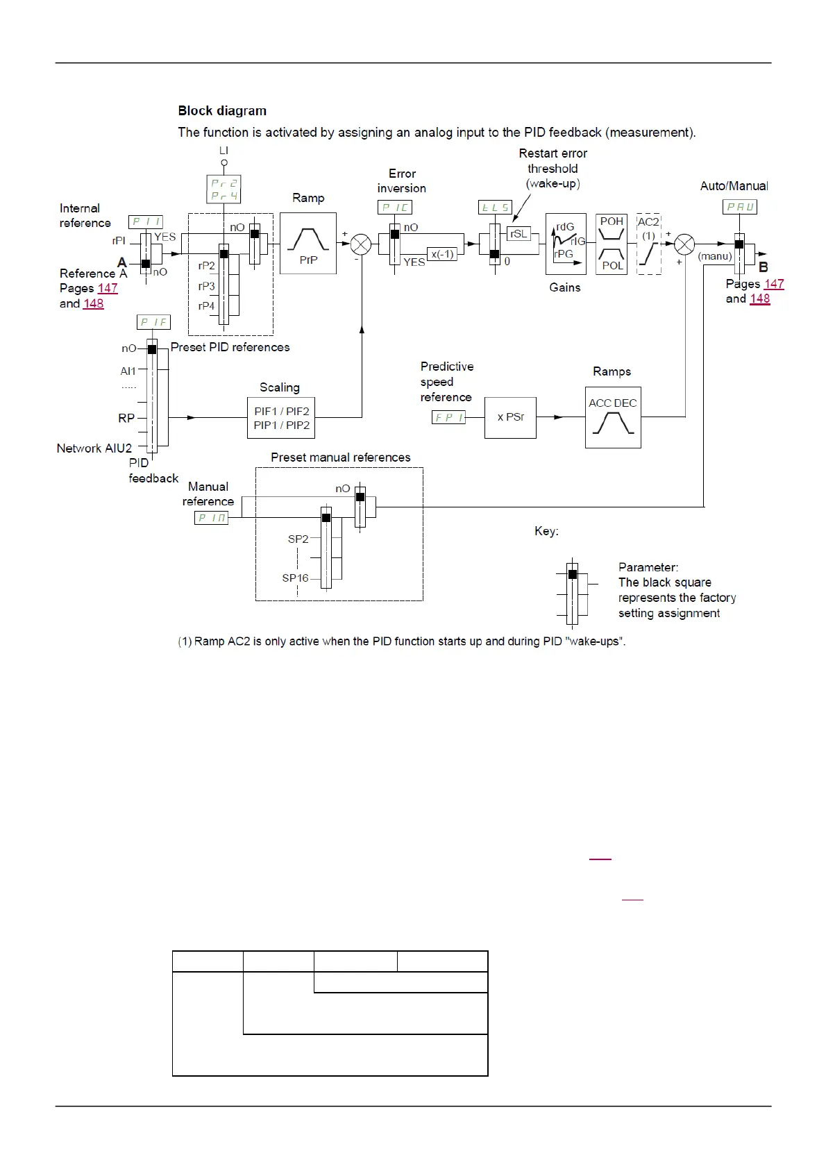
Block diagram
The function is activated by as s igning an analog input to the PID feedback (m eas urement).
Internal
reference
rPI
A
YE S
LI
Ramp
nO
+
-
Error
inversio n
nO
YE S
Restart error
threshold
(w ake-up)
0
Auto/Manual
+
+
(m anu )
Reference A
nO
Pages 147
and 148
Gains
B
Pages 147
and 148
nO
AI1
.....
RP
Preset PID references
Scaling
Predictiv e
speed
reference
Ramps
Netw ork AIU2
PID
feedbac k
Manual
referenc e
Preset manual references
nO
Key:
Param et er:
The black square
represents the factory
setting assignment
(1) Ramp AC2 is only active w hen the PID function starts up and during PID "w ake-ups".
PID feedback:
The PID feedback m ust be as s igned to one of the analog inputs AI1 to AI3, to the pulse input, according to
whether any extens ion cards have been inserted.
PID reference:
The PID reference m us t be as signed to the following param eters: Pres et references via logic inputs
(rP2,
rP3, rP4)
In accordance with the configuration of
[Act. in
tern
al PID ref.]
(
PI
I
) page 210:
Internal reference (
rP
I
) or
Reference A (
[Ref.1 channel]
(Fr1)
or
[Ref.1B channel]
(Fr1b),
see page 154).
Combination table for preset PID references:
LI
(Pr4)
LI
(Pr2)
Pr2
=
nO
Re fe rence
0
0
rPI or A
0
rPI or A
1
rP2
1 0 rP3
1 1 rP4
A predictive speed reference can be us ed to initialize the speed on res tarting the proces s.


 To Next Page