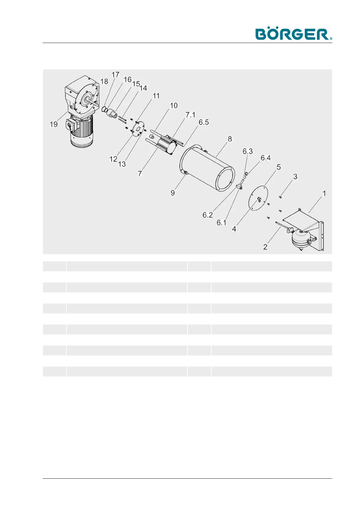
Clamping unit with pneumatic adjustment
1 Compressed-air container 8 Cover
2 Compressed-air tube 9 Hexagon socket head cap screws
3 Hexagon head screw 10 Threaded adapter, pneumatic cylinder
4 Elbow union 11 Hexagon head screw with washer
5 Plate for rotating union 12 Pressure plate, pneumatic cylinder
6.1 Rotating union 13 Hexagon head screw with washer
6.2 Double pipe nipple 14 Hexagon socket head cap screw
6.3 Socket 15 Spring guide bolt
6.4 Angle plug connection 16 O-ring
6.5 Carrier plate 17 O-ring
7 Pneumatic cylinder unit 18 Threaded rod
7.1 Compressed-air tube 19 Drive
— Read and follow the safety instructions detailed in
Ä
Chapter
2.12 “Safety instructions for maintenance and rectifying mal-
functions” on page 37.
— Empty the Börger machine as described in
Ä
Chapter 6.3.1
“Notes on repair work” on page 129.
Maintenance and repairs
BA-RC40_EN, 17.01.2024 www.boerger.de / www.boerger.com 133
 Loading...