15. Make sure that the bore holes of the auger adapter (17) are
aligned with the bore holes of the drive flange (13). For
example, use a rod to push it into the mounting flange (7) in
order to turn the brush auger (8).
16. Use the maintenance openings to tighten the hexagon head
screws (12) at the connection between the drive flange (13)
and the auger adapter (17) applying the appropriate torque.
17. Check the O-rings (18). Replace the O-rings if they show
signs of damage.
18. Install the covers of the maintenance openings (10) and
tighten the hexagon head screws (9) with washers.
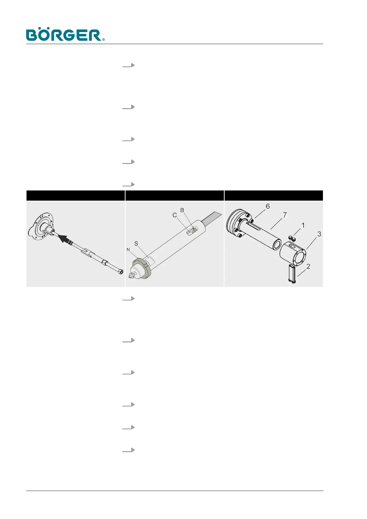
19. Insert the threaded rod (5) at the side of the drive.
Insert the threaded rod Screw on and align the drive sleeve Install the drive sleeve
20. Screw the drive pin with the slotted nut [N] onto the threaded
rod using the two wrench flats [A] until the end of the
threaded rod [B] is flush with the elongated hole [C] of the
drive pin.
21. Install the drive sleeve (3) in such a way that the elongated
hole of the drive sleeve is congruent with the elongated hole
[C] of the drive pin (4) and mounting flange (7).
22. Insert the drive block (2) with the two hexagon head screws
with washers into the drive sleeve (3) and tighten the two
hexagon head screws (1) with washers previously loosened.
23.
Install the filter press channel as described in
Ä
Chapter
6.3.5 “Changing the filter press channel” on page 150.
24.
Install the Multi Disc as described in
Ä
Chapter 6.3.4
“Changing the Multi Disc plate” on page 146.
25.
Attach the clamping unit as described in
Ä
Chapter 6.3.2
“Removing/repairing the clamping unit” on page 131.
Maintenance and repairs
BA-RC40_EN, 17.01.2024www.boerger.de / www.boerger.com162