BL702/704/706 Reference Manual
bit1
“1”
Address
Command
LSB
Start bits always“1”
MSB
T
LSB
S2
MSB
S1
bit14
“1”
bit13
“0”
bit12
“1”
bit11
“0”
bit10
“1”
bit9
“1”
bit8
“1”
bit7
“0”
bit6
“1”
bit5
“0”
bit4
“0”
bit3
“0”
bit2
“1”
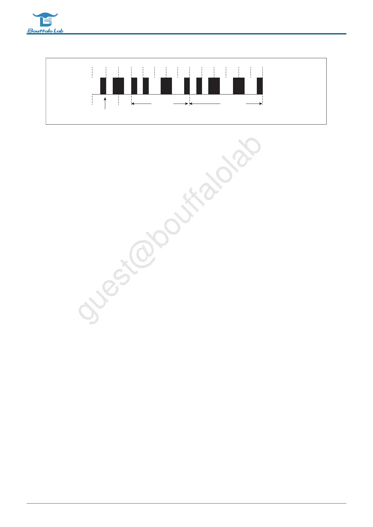
Fig. 8.4: rc5
The first two bits are the start bit, fixed to logic 1, and the third bit is the flip bit. When a key value is issued and then
pressed, the bit will be inverted. The next 5 bits are the address code and the 6 bits command code. The first two
bits are the start bit, fixed to logic 1, and the third bit is the flip bit. When a key value is issued and then pressed, the
bit will be inverted. The next 5 digits are the address code and the 6-digit command code.
It should be noted that in order to improve the receiving sensitivity, the common infrared integrated receiver head
outputs a low level after receiving a high level, so when the IR receiving function is used, the receiving flip function
must be turned on.
8.3.2 Pulse width reception
For data in any format other than the NEC and RC-5 protocols, the IR will count the duration of each high and low
level in turn using its clock, and then store the data in a 64-byte depth receiving FIFO.
8.3.3 Normal sending mode
Users can configure the corresponding configurations of the head pulse, tail pulse, logic 0 and logic 1 pulses according
to specific protocols. When setting, it is necessary to calculate the common pulse width unit of various pulses with
different widths in the protocol used, that is, the greatest common divisor, fill in the lower 12 bits of the register IRTX_-
PULSE_WIDTH, and each pulse fills its corresponding multiple in the register IRTX_PW.
IR supports a maximum of 64-bit data bits and is divided into two 32-bit registers IRTX_DATA_WORD0 and IRTX_-
DATA_WORD1.
8.3.4 Pulse width transmission
For protocols that are not suitable for normal transmission mode, IR provides a pulse width transmission method.
First calculate the common pulse width unit of the pulses of different widths in the protocol used, that is, the greatest
common divisor, and fill in the lower 12 bits of the register IRTX_PULSE_WIDTH. Then fill the register IRTX_SWM_-
PW_n(0 <= n <= 7)with multiples corresponding to the respective level widths from the first high level to the last level,
each level width multiple occupies 4-bit .
BL702/704/706 Reference Manual 165/ 375
@2021 Bouffalo Lab
 Loading...