Brooks Automation 7. Service Procedures
Part Number: PF40-DI-00010 Rev. A Replacing Servo Gripper with Pneumatic or Vacuum Gripper
Step Action
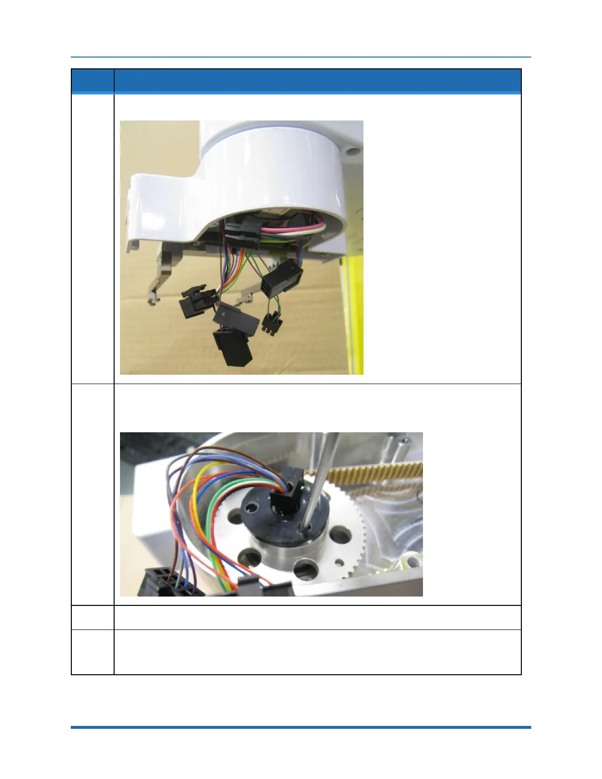
9.
Unplug the slip ring connectors inside the servo gripper.
10.
Rotate the slip ring slightly to expose the M2 counter bores in the J4 output pulley.
Using a M1.5 hex driver, remove the (6) M2 X 16 mm SHCS that attach the gripper. Lower the gripper
gently while feeding the slip ring connectors through the hole in the gripper housing.
11.
Remove the slip ring.
12.
Loosen the M3 screw that attaches the harness cable clamp to the J3 output pulley until the clamp can
be pulled all the way up to provide access to the M3 X 8 mm BHCS that closes the clamp.
Remove this screw and the rubber pad on the harness.
Copyright © 2023, Brooks Automation
148