Brooks Automation 7. Service Procedures
Part Number: PF40-DI-00010 Rev. A Replacing Servo Gripper with Pneumatic or Vacuum Gripper
Step Action
20.
Install the Delrin bumper for sliding stop in the threaded hole under the end of the outer link with 4-40 X
3/8 mm Steel Socket Head Cap Screw and Loctite 222.
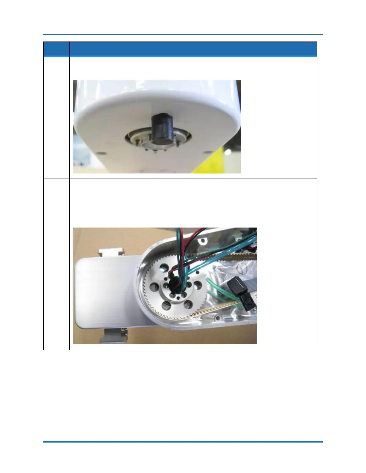
21.
Add the slider for pneumatic or vacuum gripper to the top of the gripper and attach the gripper to the J4
output pulley by tightening the (6) M2 SHCS after threading the wires and hoses from the gripper
through the pulley.
Ensure that the dowel pin in the J4 pulley fits into the notch in the gripper to orient the gripper.
Be very careful not to pinch any wire between the gripper and the pulley.
Copyright © 2023, Brooks Automation
152