BRP-Rotax
INSTALLATION MANUAL
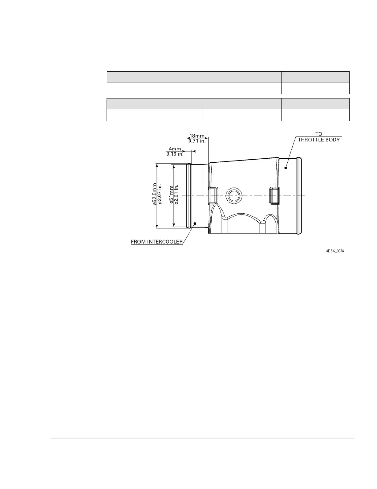
Connection on intercooler:
Interface Parameter
Min. Max.
Slip-on length 32 mm (1.26 in.)
-
Intercooler to
overboost valve
Interface Parameter
Min. Max.
Slip-on length 18 mm (0.71 in.)
Figure 6.6: Overboost valve
Connection on throttle body: Install the delivered hose (scope of supply) to the correct
side of the overboost valve, recheck if it fits.
ELECTRICAL INTERFACES
PCV sockets The appropriate connectors on the wiring harness as well as the corresponding sockets
on the PCV are color coded.
To avoid inappropriate behavior of the wastegate the correct linkage needs to be ensured.
Effectivity: 916 i A / C24
Edition 0/Rev. 1
72–60–00
Page 9
December 01 2023

 Loading...


