BRP-Rotax
INSTALLATION MANUAL
SYSTEM DESCRIPTION
For a detailed system description refer to the latest issue of the Operators Manual (OM).
SYSTEM LIMITATIONS
NOTICE
Consumer cables must NOT be routed alongside the ignition cables. There is a
risk of electromagnetic interference.
Valid installation
positions
The Fusebox must not be installed in the cockpit. Installation is only allowed in the engine
compartment.
Component tem-
peratures
limitation
Limitations see Chapter 00-00-00 Approval of electric and electronic components.
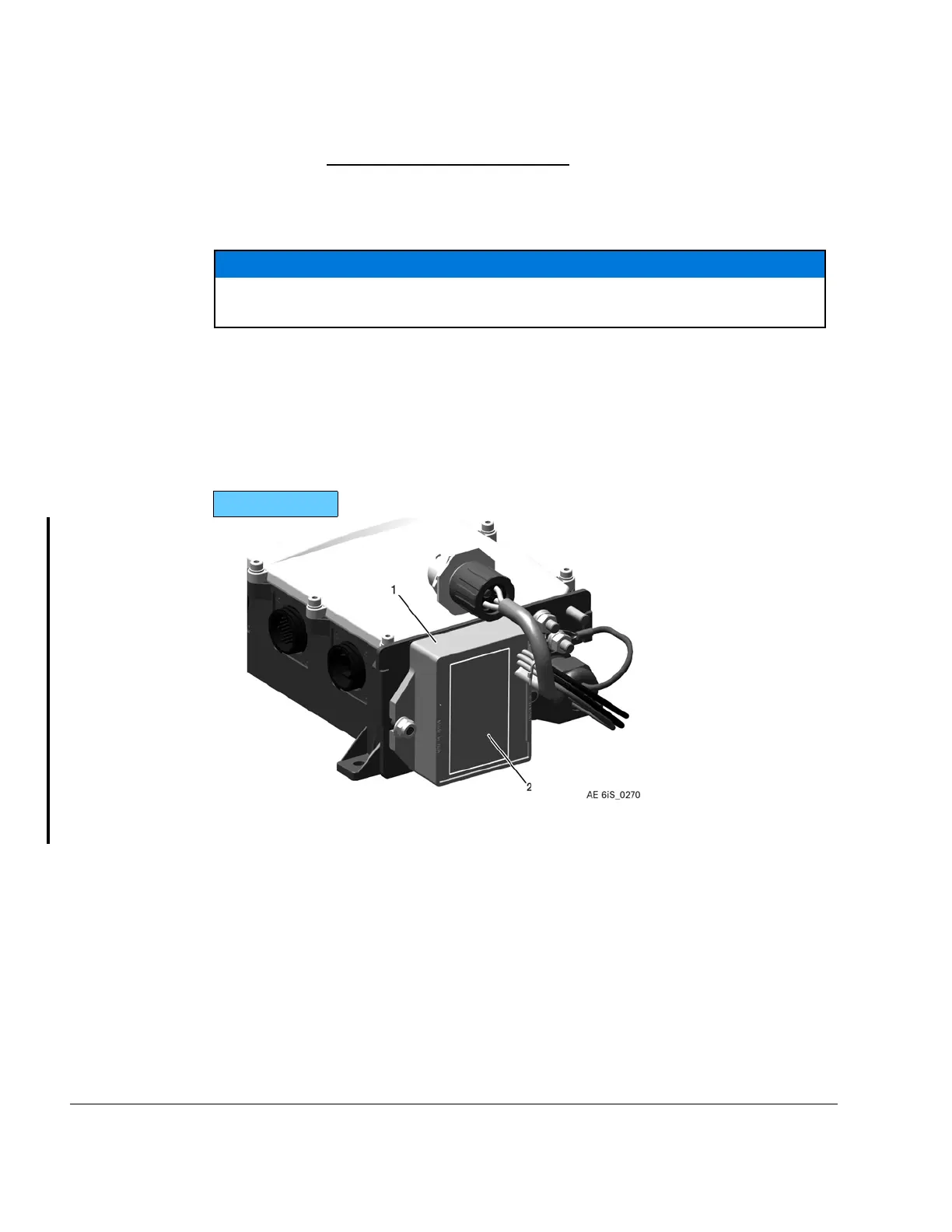
The Regulator temperature must be measured as shown within the following figure:
916 i TYPE A
Figure 3.3: Regulator temperature measurement area
1
Rectifier regulator
2
Component temperature measurement
area
24–00–00
Page 4
December 01 2023
Effectivity: 916 i A / C24
Edition 0/Rev. 1

 Loading...


