BRP-Rotax
INSTALLATION MANUAL
ELECTRICAL INTERFACES – 916 I TYPE C24
Harness Interface
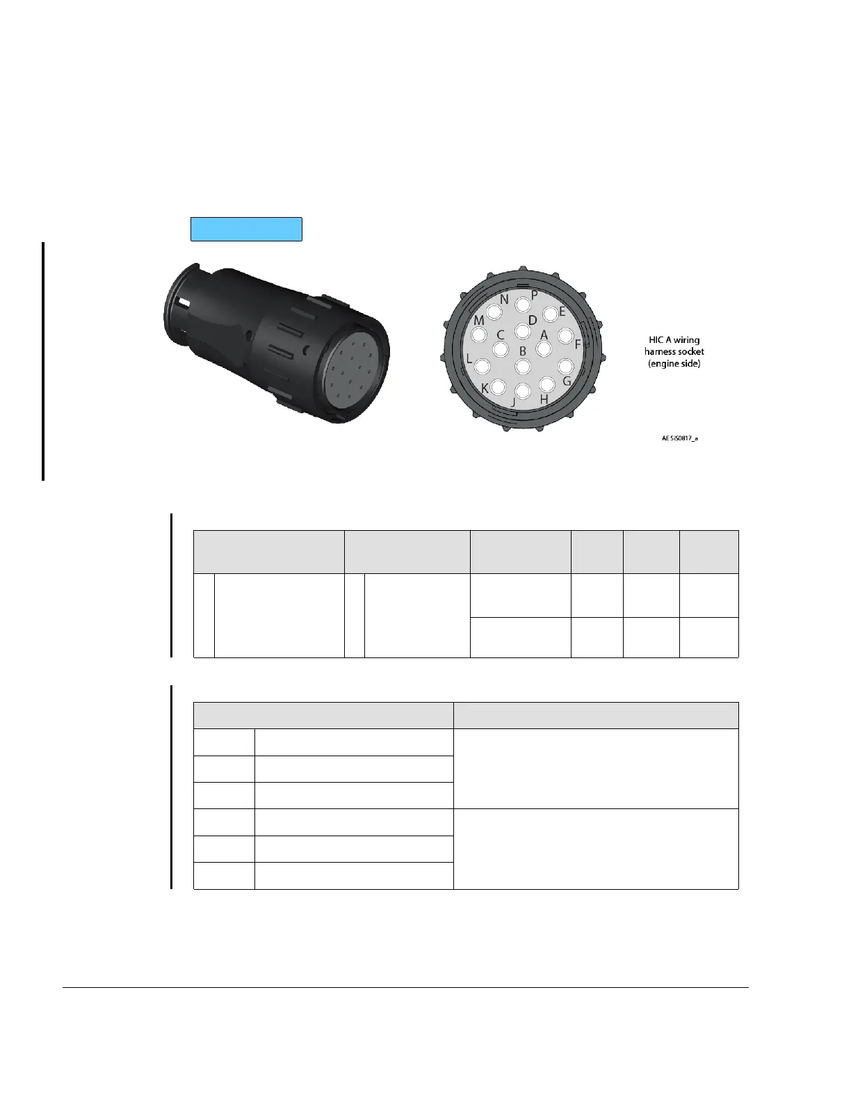
Connector A
The HIC Connector A is equipped with a Maintenance CAN interface, a Display CAN inter-
face and terminals which can be used to actuate a warning lamp indicating the current sta-
tus of the ECU Lane A. Interfaces to control elements are described in Chapter 76-00-00.
916 i TYPE C 24
Figure 10.7: HIC A connector
Warning lamp
Terminal (Supply)
Terminal
(Ground)
Interface
Parameter
Min. Max. Nomi-
nal
A
SUPP_WARN_
LAMP_A
D
WARN_
LAMP_A
Nominal
voltage
12 V
Nominal
current
120
mA
CAN Interfaces:
Terminal
Specification
C CAN_GND_1_A Display CAN Lane A
L
CAN_LOW_1_A
M
CAN_HIGH_1_A
B
CAN_GND_2_A Maintenance CAN Lane A
J
CAN_LOW_2_A
K
CAN_HIGH_2_A
Connector: HIC Connector A (included in the engines scope of delivery).
The HIC Connectors must be mounted according to the procedure prescribed in Chapter
76-00-00.
77–00–00
Page 10
December 01 2023
Effectivity: 916 i A / C24
Edition 0/Rev. 1

 Loading...


