BRP-Rotax
INSTALLATION MANUAL
INSTALLATION NOTES
General The representation of components in this chapter which are not within scope of the deliv-
ery is only symbolic. The design shown in this chapter does not represent a specified exe-
cution but should support the understanding of the system.
The final design, the selection and specification of parts according to the respective appli-
cable regulations, the consideration of the system limitations and interface description as
well as the comprehension of the operating limits in every operational state is in the re-
sponsibility of the aircraft manufacturer.
The aircraft manufacturer has to make sure that the operating limits given in the Operators
Manual (OM) can be supervised by the pilot. The execution of the installation must allow
the operation of the engine according to the Operators Manual (OM).
INSTALLATION OVERVIEW
916 i TYPE A
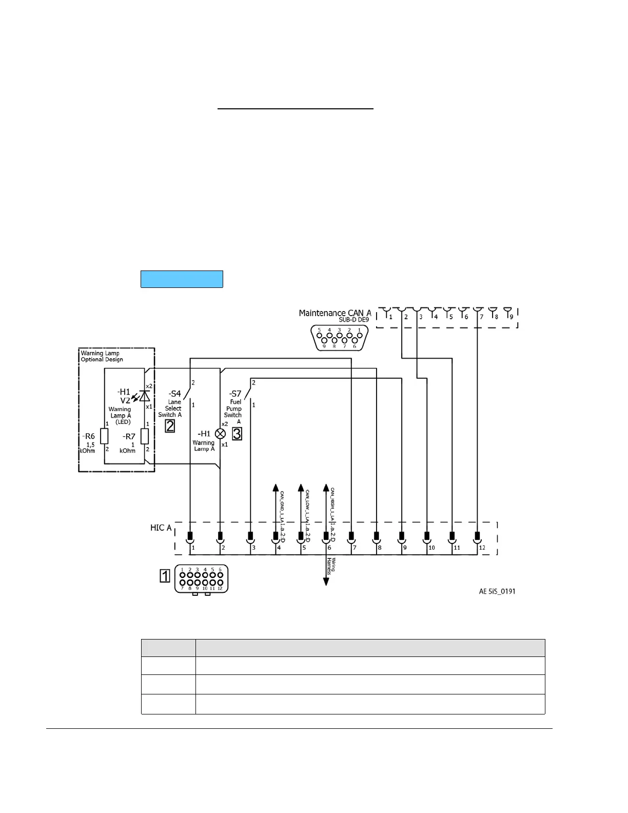
Figure 9.15: Harness Interface Connector A-Schematic
Part Function
1
Harness Interface Connector A
2 Lane Select Switch A (-S4)
3 Fuel Pump Switch A (-S7)
76–00–00
Page 16
December 01 2023
Effectivity: 916 i A / C24
Edition 0/Rev. 1

 Loading...


