EasyManuals Logo

BRP ROTAX 916 i A Series Installation Manual

BRP ROTAX 916 i A Series
223 pages
To Next Page IconTo Next Page
To Previous Page IconTo Previous Page
Page #208 background imageLoading...
Page #208 background image
BRP-Rotax
INSTALLATION MANUAL
INTERFACE DESCRIPTION
INTERFACE OVERVIEW
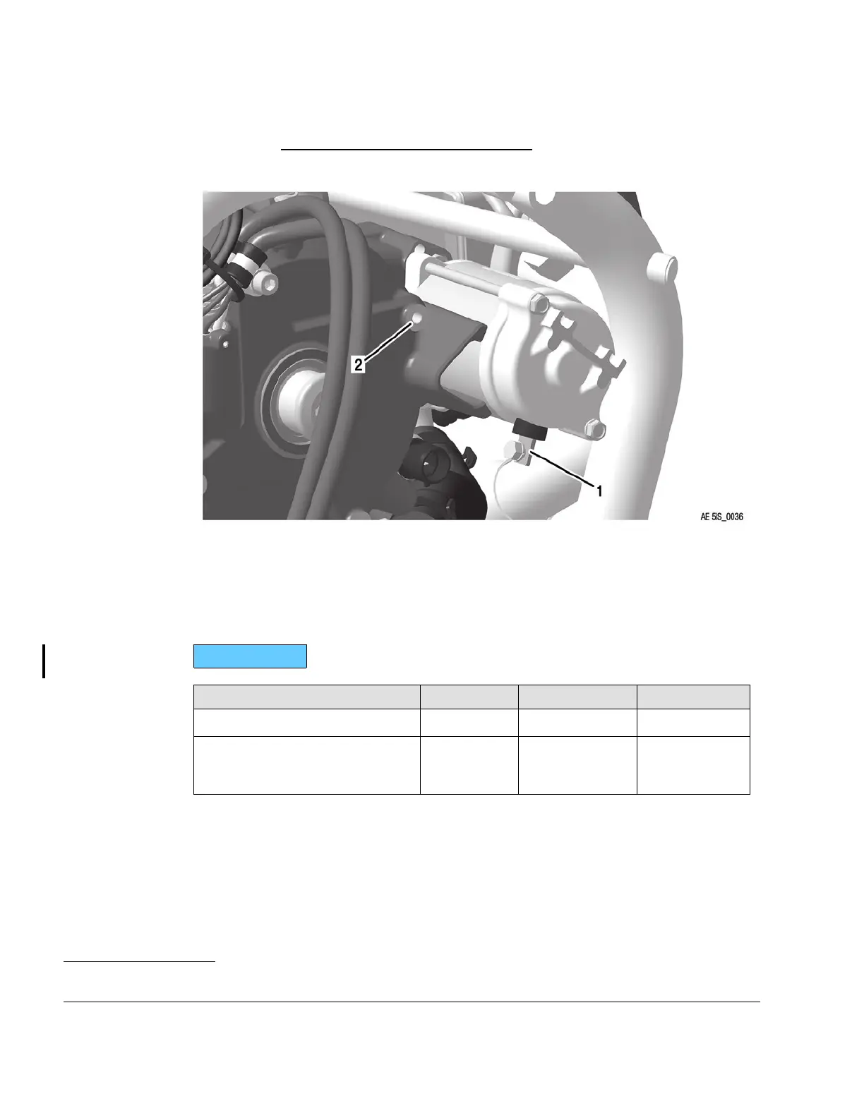
Figure 13.2: Starter interfaces
1 Positive terminal 2
Negative terminal
ELECTRICAL INTERFACES
Positive
terminal
916 i TYPE A
Interface Parameter Min. Max. Nominal
Input voltage: 12 V
Input load:*
* for resistance of starter circuit
Rsmax = <20 mOhm
20 A 350 A
4
The terminal must be conducted as M5 screw connection suitable for cable lug according
to DIN 46225.
Tightening torque: Min. 3 Nm (27 in.lb) Max. 5 Nm (44 in.lb).
80–00–00
Page 4
December 01 2023
Effectivity: 916 i A / C24
Edition 0/Rev. 1
4. When electric starter is activated

Table of Contents

Other manuals for BRP ROTAX 916 i A Series

Questions and Answers:

Question and Answer IconNeed help?

Do you have a question about the BRP ROTAX 916 i A Series and is the answer not in the manual?

BRP ROTAX 916 i A Series Specifications

General IconGeneral
BrandBRP
ModelROTAX 916 i A Series
CategoryEngine
LanguageEnglish

Related product manuals