BRP-Rotax
INSTALLATION MANUAL
INTERFACE OVERVIEW — 916 I TYPE C24
916 i TYPE C24
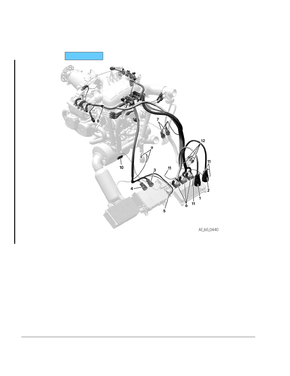
Figure 9.8: Engine Management System (EMS)– Interfaces
1
Harness Interface Connector A (HIC A)
(electrical Interface)
2
Harness Interface Connector B (HIC B)
(electrical Interface)
3
X1 Connector (electrical Interface)
4
X2 Connector (electrical Interface)
5
Regulator A (electrical Interface)
6
ECU (electrical, mechanical Interface)
7
AAPTS (electrical, mechanical
Interface)
8
Wiring harness
9
Starter relay connectors (electrical
Interface)
10
Fuel pump connectors (electrical
Interfaces)
11
Ring terminal Ground cables
12 PCV Connector
76–00–00
Page 10
December 01 2023
Effectivity: 916 i A / C24
Edition 0/Rev. 1

 Loading...


