BRP-Rotax
INSTALLATION MANUAL
INSTALLATION NOTES
The representation of components in this chapter which are not within scope of the deliv-
ery is only symbolic. The design shown in this chapter does not represent a specified exe-
cution but should support the understanding of the system.
The final design, the selection and specification of parts according to the respective appli-
cable regulations, the consideration of the system limitations and interface description as
well as the comprehension of the operating limits in every operational state is in the re-
sponsibility of the aircraft manufacturer.
The aircraft manufacturer has to make sure that the operating limits given in the Op-
erators Manual (OM) can be supervised by the pilot. The execution of the installa-
tion must allow the operation of the engine according to the Operators Manual
(OM).
INSTALLATION OVERVIEW
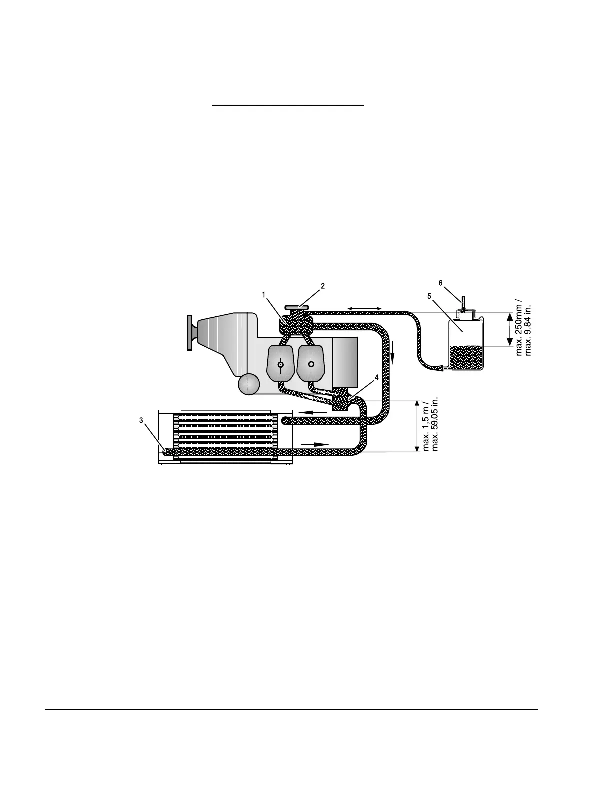
Figure 8.8: Cooling system schematic
1
Expansion tank
2
Pressure cap
3 Radiator 4
Water pump
5 Overflow bottle 6 Vent
Radiator In an installation as depicted with the radiator in a higher position than the standard sup-
plied expansion tank, a water accumulator has to be fitted instead of the expansion tank.
Additionally a suitable expansion tank has to be installed at the highest point of the cooling
circuit
In order to support the deployment of the radiator's full capacity, the radiator should be
connected with the upper connection to the suction side in direction to the water pump.
Otherwise, air bubbles may accumulate, resulting in reduced cooling capacity (see setup
depicted in Cooling system schematic).
75–00–00
Page 10
December 01 2023
Effectivity: 916 i A / C24
Edition 0/Rev. 1

 Loading...


