BRP-Rotax
INSTALLATION MANUAL
OIL TANK INTERFACES
Oil tank inlet and
outlet
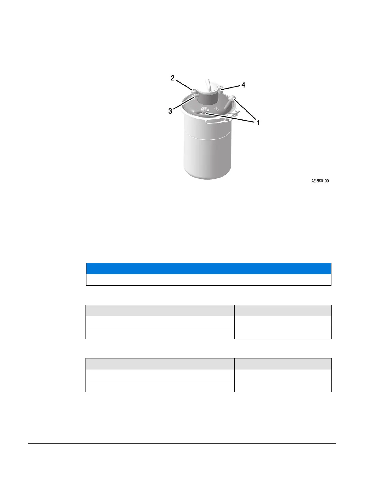
Figure 12.7: Oil tank interfaces
1 Oil tank inlet 2 Oil tank outlet
3 Vent socket 4
Oil tank inlet (turbo charger)
NOTE
The oil tank cover is also marked: IN — oil tank inlet, OUT — oil tank outlet.
NOTICE
Both oil tank inlets must be connected with the oil return outlets.
2x Oil tank inlet
Interface Parameter
Value
Screw socket M18x1.5 or 3/4–16 UNF
Tightening torque
25 Nm (18 ft. lb)
Oil tank outlet
Interface Parameter
Value
Screw socket M22x1.5 or 7/8–14 UNF
Tightening torque
25 Nm (18 ft. lb)
79–00–00
Page 10
December 01 2023
Effectivity: 916 i A / C24
Edition 0/Rev. 1

 Loading...


