BRP-Rotax
INSTALLATION MANUAL
INTERFACE DESCRIPTION
INTERFACE OVERVIEW
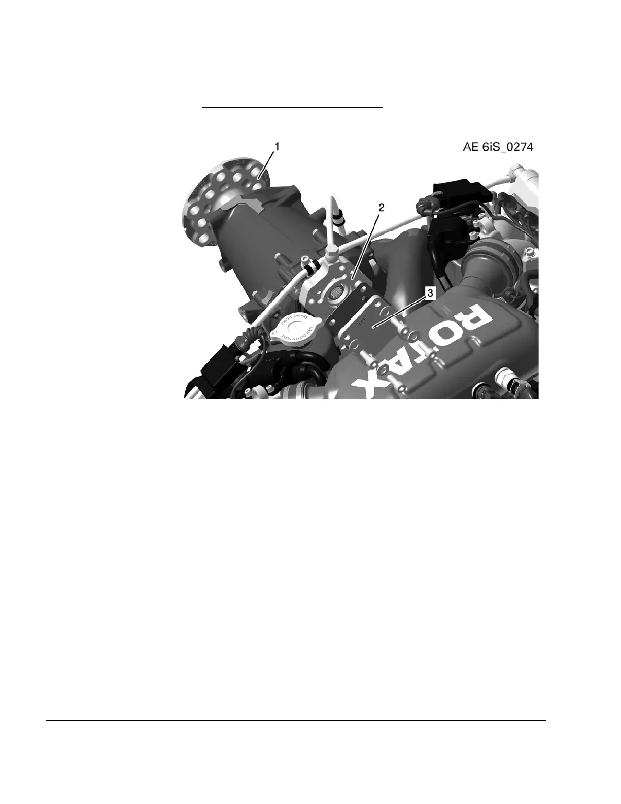
Figure 4.3: Interface (configuration 3)
1
Propeller shaft (mechanical. Interface)
2
Governor flange (hydraulic. Interface)
3
Cover plate
NOTE
The cover used for delivery needs to be removed before engine operation. The
cover may not be used in operational condition.
61–00–00
Page 4
December 01 2023
Effectivity: 916 i A / C24
Edition 0/Rev. 1

 Loading...


