BRP-Rotax
INSTALLATION MANUAL
INTERFACE DESCRIPTION– 916 I TYPE A
INTERFACE OVERVIEW
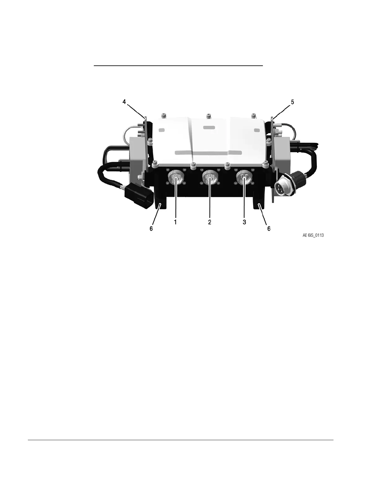
Figure 3.5: Fusebox connections, TYPICAL
1
X1 Connector (electrical interface)
2
X2 Connector (electrical interface)
3
X3 Connector (electrical. interface)
4
Regulator Plate A (electrical interface)
5
Regulator Plate B (electrical interface)
6
Fusebox mounting points (mechanical
interface)
ELECTRICAL INTERFACES
The seals supplied with the Fusebox must be inserted into the X1,X2 and X3 Connector
(Fusebox side) to enable a good connection between plug and socket and thus avoid un-
necessary vibrations and misalignment of connector pins.
Fusebox –X1, X2
Connector
The X1 and X2 ensure the power distribution to the EMS System. Both plugs must be con-
nected with mating sockets on the (engine-) wiring harness. The connectors are not inter-
changeable and are marked on the wiring harness side.
Fusebox–X3
Connector
For information on the X3 Connector, see the relevant SI-PAC-012.
24–00–00
Page 6
December 01 2023
Effectivity: 916 i A / C24
Edition 0/Rev. 1

 Loading...


