BRP-Rotax
INSTALLATION MANUAL
916 i TYPE C 24
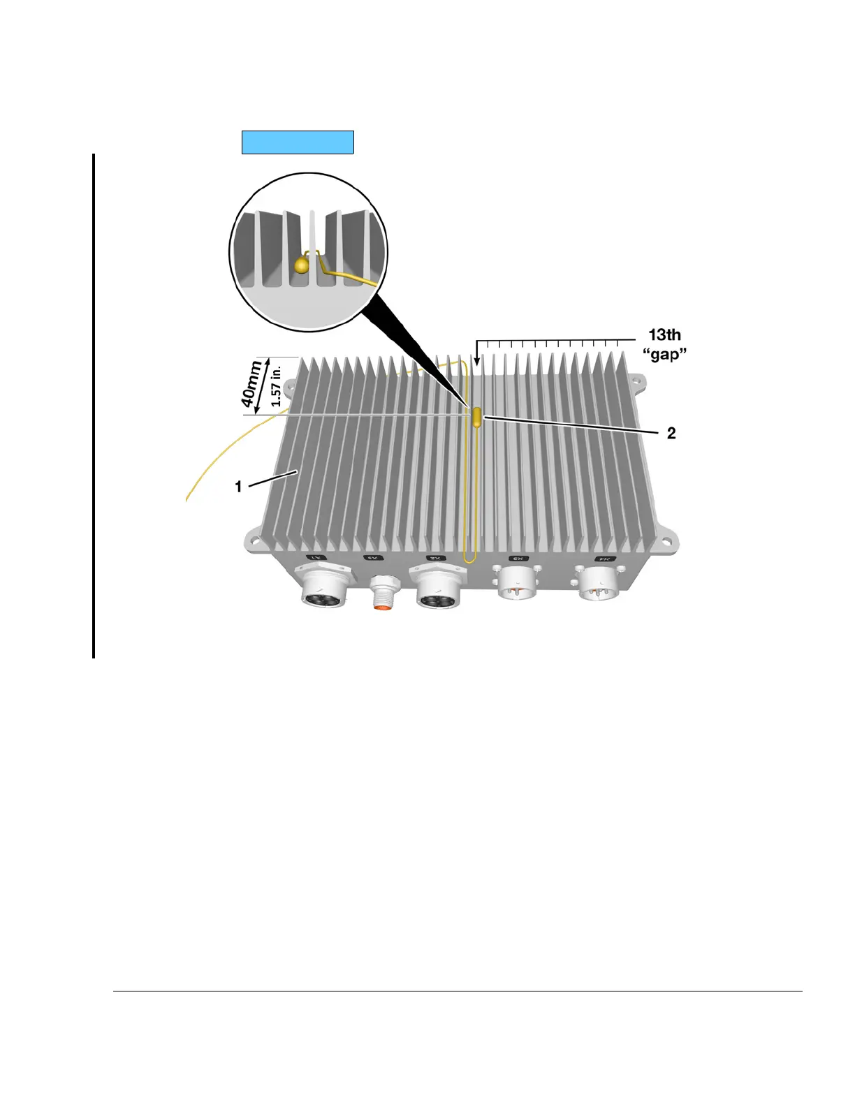
Figure 3.4: Regulator temperature measurement area
1
28 V AC-DC Converter assy.
2
Component temperature measurement
area
Separation of
EMS and Airframe
circuit
A connection between regulator plate A (EMS ground) and airframe ground should only
be done during supply of the EMS System by an external power source (e.g. during en-
gine start). Although it would have no impact on the redundancy of the EMS, the fault tol-
erance of the system will be degraded if the EMS ground is connected permanently with
the airframe ground.
Effectivity: 916 i A / C24
Edition 0/Rev. 1
24–00–00
Page 5
December 01 2023

 Loading...


