BRP-Rotax
INSTALLATION MANUAL
Terminal (Supply) Terminal (Ground) Interface
Parameter
Min. Max. Nomi-
nal
1
LANE_SEL_
SW_A_1
7
LANE_SEL_SW_
A_2
Nominal
Voltage
12 V
Nominal
Current
7.5 A
3
SIG_FUEL_
PUMP_1
9
GND_FUEL_
PUMP_1
Nominal
Voltage
12 V
Nominal
Current
10 A
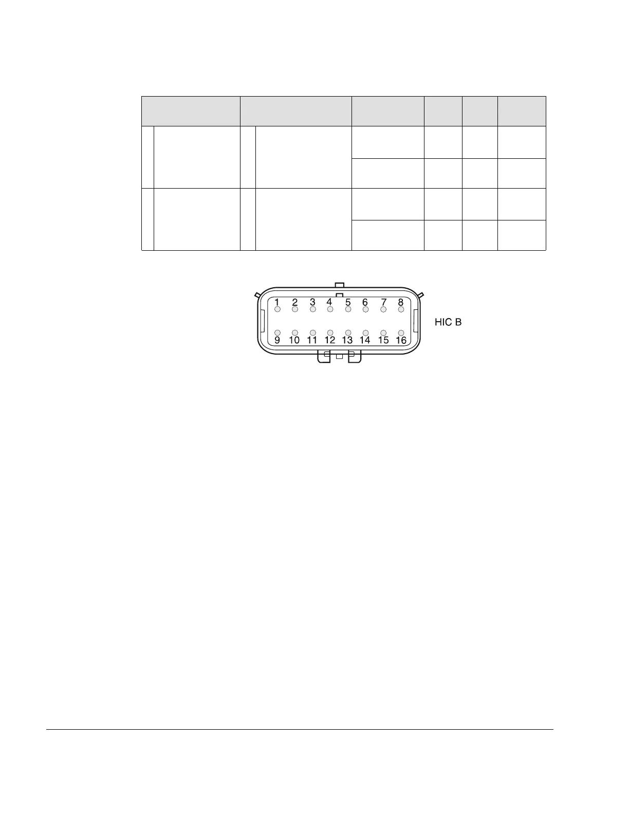
Harness Interface
Connector B
Figure 9.6: HIC B connector
In case the EMS is powered by an external power source or by one of the internal
generators:
• A connection between Terminal 1 and Terminal 9 will power ECU Lane B
• A connection between Terminal 3 and Terminal 11 will power Fuel Pump 2
• A connection between Terminal 4 and Terminal 12 will actuate the Starter Relay
76–00–00
Page 8
December 01 2023
Effectivity: 916 i A / C24
Edition 0/Rev. 1

 Loading...


