2-60 2007 Buell Lightning: Chassis
HOME
DISASSEMBLY
NOTE
Carefully mark all bearing components as they are removed
so that they may be returned to their original locations. Do not
intermix bearing components.
Swingarm
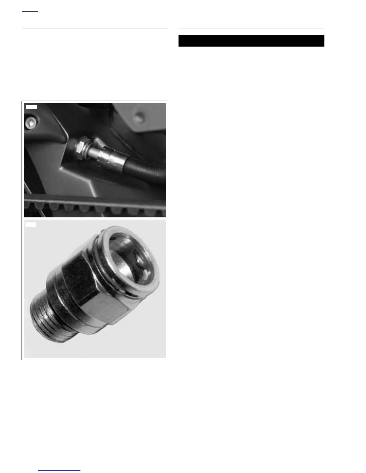
1. See Figure 2-85. Remove oil line fittings from swingarm.
2. See Figure 2-84. Remove swingarm bearings (5) using
slide hammer (SNAP-ON Part No. CJ1275 or equivalent)
and 3/4 in. bearing remover and spacer.
3. Remove shock mount bushings (3) and sleeve.
4. Remove stone guard. See 2.36 BELT GUARDS.
NOTE
See Figure 2-84. Remove swingarm bearings (5) only if
replacement is required. The complete bearing assembly
must be replaced as a unit when replacement is necessary.
Do not intermix bearing components.
CLEANING AND INSPECTION
11WARNING1WARNING
Compressed air can pierce the skin and flying debris
from compressed air could cause serious eye injury.
Wear safety glasses when working with compressed air.
Never use your hand to check for air leaks or to deter-
mine air flow rates. (00061a)
1. Thoroughly clean all components in solvent. Blow dry
with compressed air.
2. Carefully inspect all bearing components for wear and/or
corrosion. Replace complete bearing assembly if any
component is damaged.
3. Check that swingarm is not bent or twisted. Replace if
damaged.
ASSEMBLY
Swingarm
1. See Figure 2-84. Install
new
shock mount bushings (3).
2. Install
new
bearings (5) and spacer (4) with BEARING
INSTALLER (Part No. HD-44060) by lightly seating
spacer.
NOTES
●
The left side bearing must be installed first and fully
seated.
●
Swingarm bearings should be replaced as a unit. Do not
intermix components. Mark all components so they may
be correctly installed.
3. See Figure 2-85. Install oil line fittings on swingarm with
new
o-rings. Tighten to 108-156
in-lbs
(12-17.6 Nm).
See 3.10 OIL LINE FITTINGS.
4. See Figure 2-84. Install drain plug (8). Tighten to 26-
29 ft-lbs (35-39 Nm).
Figure 2-85. Jiffy Tite, Quick Disconnect Oil Line Fittings
11488
10369