2007 Buell Lightning: Engine 3-45
HOME
Cylinder Head Assemblies
NOTE
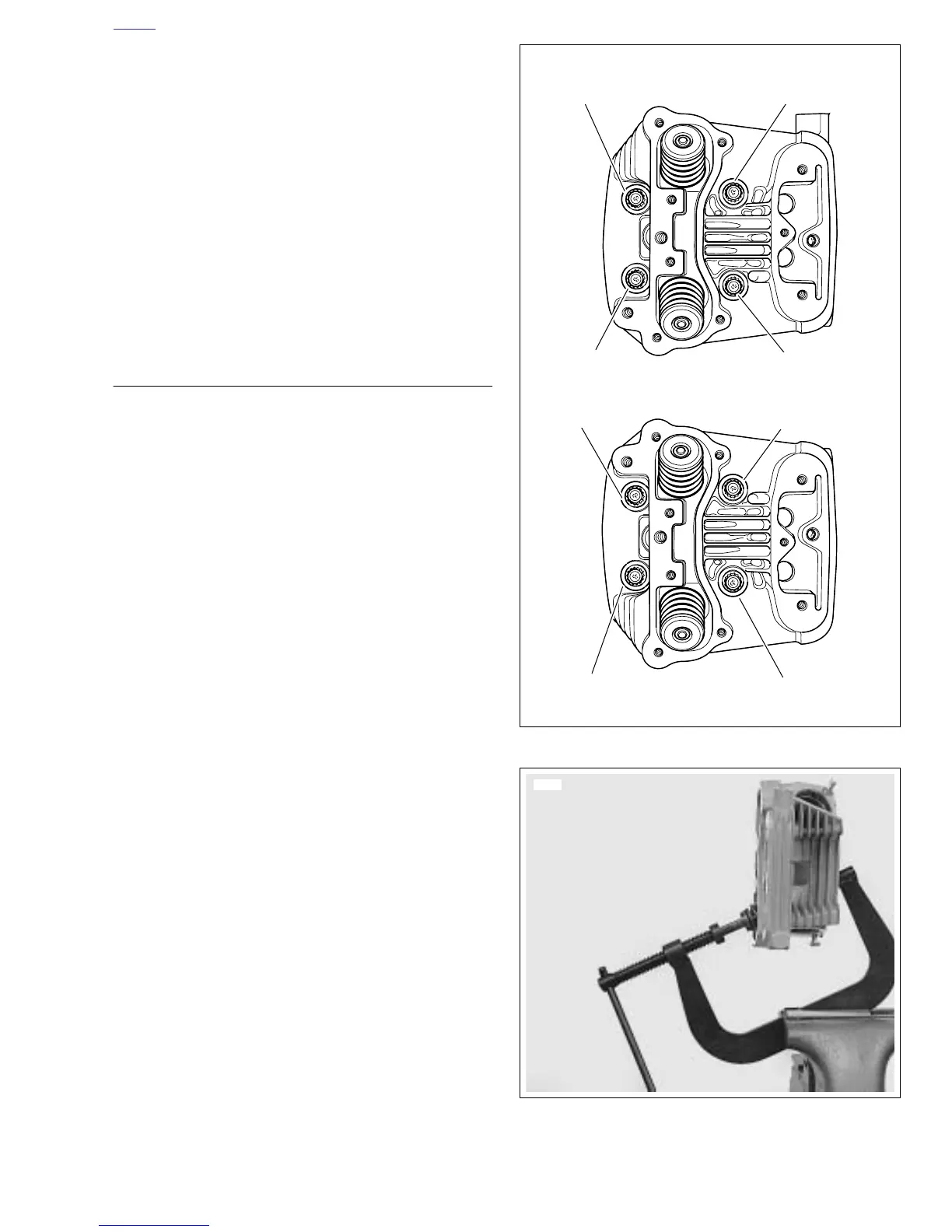
See Figure 3-59. Distortion to the head, cylinder and crank-
case studs may result if head screws are not loosened (or
tightened) gradually in the sequence shown.
1. See Figure 3-59. Loosen each head screw 1/8-turn fol-
lowing the sequence shown.
a. Continue loosening in 1/8-turn increments until
screws are loose. Remove head screws.
b. Remove cylinder head, head gasket, and o-rings.
2. Discard head gasket.
3. See Figure 3-56. Remove push rod cover, gasket and
valve tappets.
DISASSEMBLY
1. See Figure 3-60. Clamp VALVE SPRING COMPRES-
SOR TOOL (Part No. HD-34736B) in vise.
2. See Figure 3-60. Compress valve spring with VALVE
SPRING COMPRESSOR.
3. See Figure 3-61. Remove valve keepers, upper collar
and valve spring. Mark valve keepers for reassembly in
their original locations.
4. Use a fine tooth file to remove any burrs on the valve
stem at the keeper groove.
5. Mark valve to ensure that it will be reassembled in the
same head. Remove valve, valve stem seal and lower
collar assembly by hand. No special tools are required to
remove valve stem seal and lower collar assembly.
6. Repeat the above procedure for the other valves.
Figure 3-59. Head Screw Loosening/Tightening Sequence
Figure 3-60. Valve Spring Compressor
(Part No. HD-34736B)
Rear Cylinder
Front Cylinder
3rd
2nd
1st
4th
1st
2nd
3rd
4th
x0128x3a